Part 3 – Further Refinements for Version 3
In Part 1, we uncovered the excavator’s base design and finished that iteration as Version 1. In Part 2, we further refined the design by addressing key areas for improvement of overall functionality for Version 2. Version 2 introduces features that made for the excavator to be easily disassembled. In Version 3, we will outline the final steps toward completing the project. This will focus on optimizing the functional design to make the parts easier to 3D print while significantly reducing filament usage.
Here’s a brief overview of the specific areas we’ll be improving in Version 3. We’ve reduced the overall filament required by making modifications to the excavator arms and base. Additionally, splitting other components into two attachable pieces improved 3D printing orientation.
Try it out yourself
If you want to jump right in and 3D print the excavator for yourself, you can download the files from here.
Filament Reduction
The overarching goal of version three was to maximize filament efficiency while preserving the excavator’s overall shape and geometry. The final design, soon to be revealed, mirrors its predecessors at first glance. However, a closer inspection highlights the deliberate refinements made to remove as much excess filament as possible.
Excavator Arms
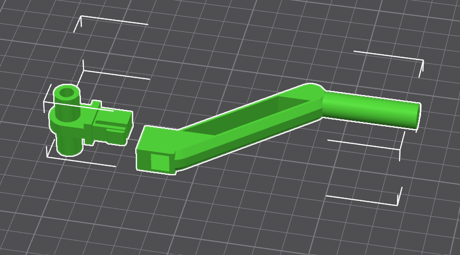
In Version 2, the cross section of the arms had been cylindrical. This meant that even laying it along it’s flattest plane would still require auto generated supports to build the shape as it printed. Addressing this, the arm, connection hole, and lever now sits flush on a single plane.
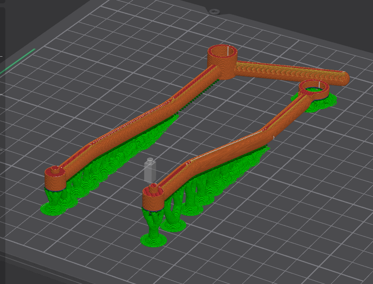
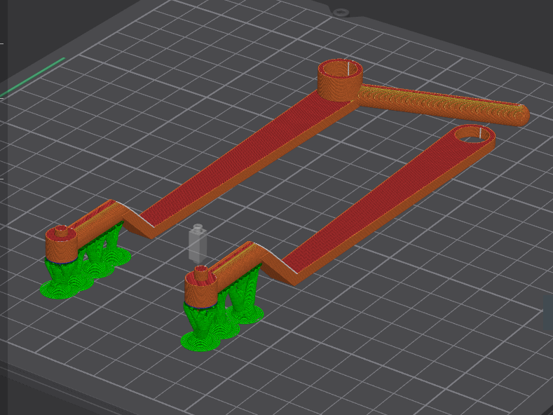
The arm lies flat on the print bed for a longer portion of its length. The hinge end that connects to the shovel angles upward off the print bed. In earlier versions of the arm, this angled transition from the connection hole to the shovels hinge was more gradual. This resulted in it lifting form the bed for it’s full length. This older version required more auto generated supports compared to the arms form Version 3.
Excavator base
The excavator base retains its circular diameter to maintain balance. The overall dimensions of the base is necessary, however, the solid fill of it is not. In Version 2, the design prints the entire footing as a solid piece. This provides a satisfying sense of weight but wasted a significant amount of filament. Users who want a heavier feel can add extra mass to the base when printing the model. In Version 3, the base design substantially hollows out the footing to reduce filament usage.
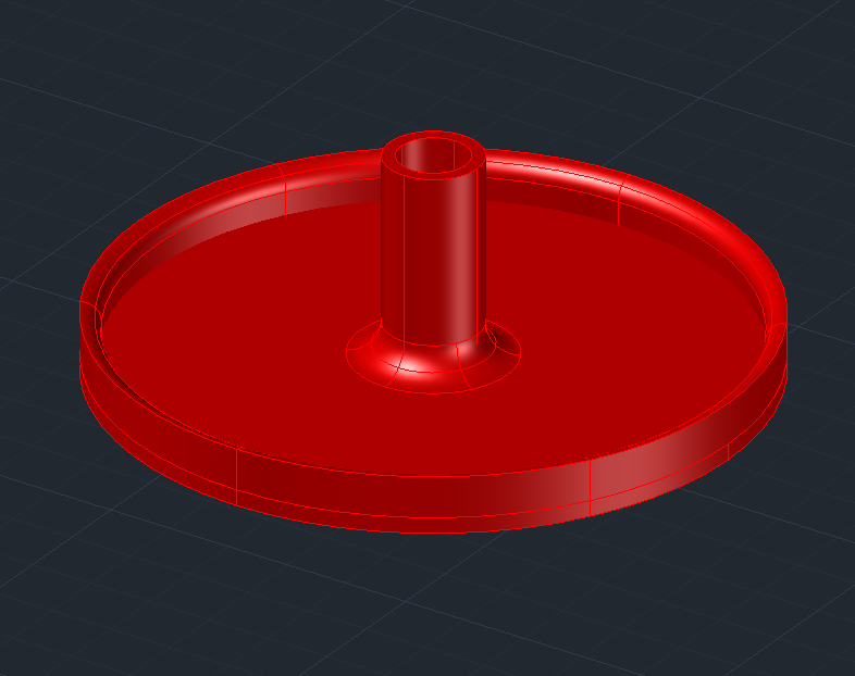
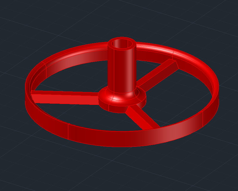
Now, the outer ring of the base is connected to the central shaft by three prongs. Let’s give a comparison to represent the filament reduction between the two versions. On my specific printer and slicer settings, the filament weight of the Version 2 base is 24.53 grams and printing time is 44 minutes. Comparing this to Version 3, it’s filament weight is 13.1 grams with a printing time of 34 minutes. A fairly well done improvement all around.
Excavator post
In version 2, the excavator post took the shape of a cylindrical shaft that has a straight length followed by a bend around the radius. At the end of this shaft rests the mechanism that holds the arms in place.
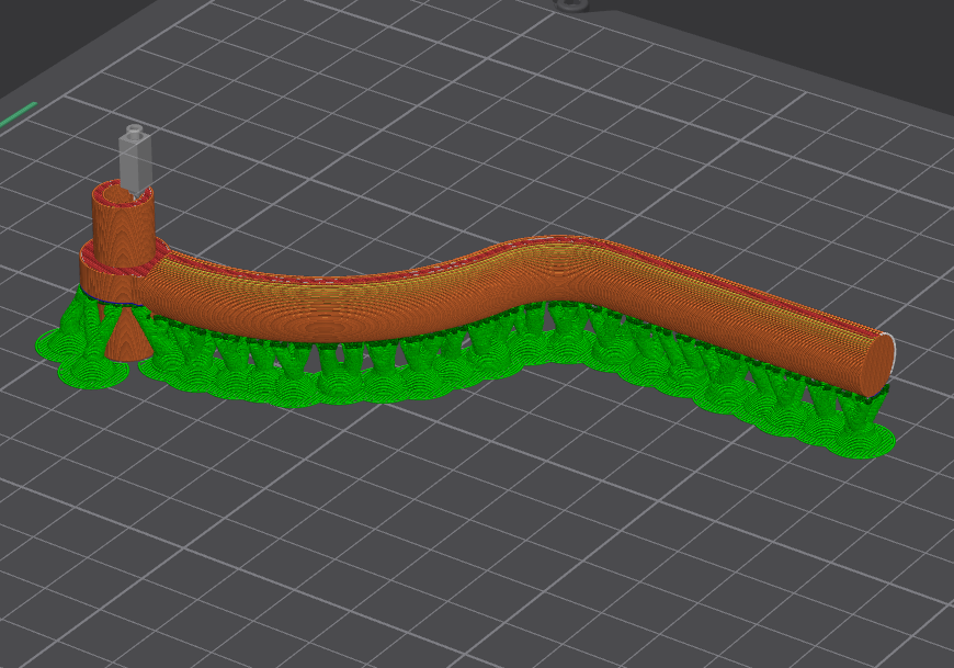
As mentioned earlier, the cross section of a circle does not lay flat on the print bed and requires additional auto generated supports to print the shape. After iterating a coupe of times, I resulted in the best compromise in material reduction. Version 3’s post retains the cylindrical shape for insertion into the base, but takes on a different shape from there. It angles out at a near 45 degree angle, consisting of two parallel supports, leaving the post hollow in it’s middle. The design of the 45-degree length prints without supports, described in its cross section.
The shape of it’s cross section consists of 60 degree risers. This is followed by a straight edge, then transitions back into 60 degree angles. This steep angle comes close enough to a vertical line where it doesn’t require auto gen supports to build up it’s shape.
You’ll notice that the end of the post still requires some minimal auto generated supports. This is to help build up an opening to insert a new component. This new component is also the next technique that aided allowing the post to print relatively flat on the bed. Which is to separate the arm connection shafts from the post entirely.
Arm to Post Connection
Attachable component
In Version 2, the design connects the arm shafts and post as a single piece. With this being the case, the shaft lifts decently high off the print bed. The excessive height contributed to requiring too many auto generated supports. Version 3 mitigates this problem by separating the arm shafts from the post as a separate component, which connects together after the completed print.
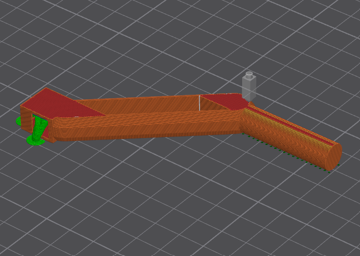
Separating the arm shafts from the post allows the smaller part to be oriented for optimal print strength. While requiring fewer supports, reducing filament waste compared to printing a larger combined piece.
The orientation of the arm shaft piece, as shown in the image below, is essential because it allows each layer to print a complete circular cross-section of the shafts, improving overall strength. It also allows for the pegs of the snap connection to run the printed lines along its length. This allows the pegs to better resist snapping due to bending forces encountered during insertion into the hole at the top of the post.
As an additional benefit of the arm shaft piece, it allows for the entire make of the shovel, arms and levers to be modular. This leaves it open to possibilities of attaching the mechanism onto something other than a post and base for a desk toy. It got me thinking about what else I could attach it to, as I may come back to this design later to give it modular utility for future designs.
An additional benefit of the arm shaft piece is that it makes the shovel, arms, and levers fully modular. This modularity opens up the possibility of attaching the mechanism to something other than the post and base for other applications beyond the desk toy. It also got me considering for future adaptations, as I may revisited it for cross modularity between future designs.
Rivet
I redesigned the rivet to improve functionality rather than reduce filament usage. In Version 2, the overall design reliably secured the excavator arms to the assembled post. However, the rivet did not fit snugly in place, and a small amount of force could pull it out of its hole. To resolve this issue, I increased the size of the stopper at the end of the pegs.
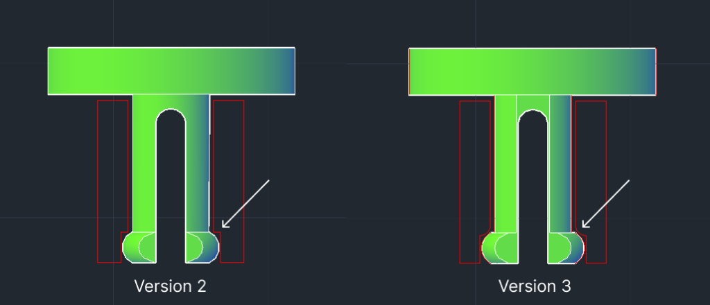
I extended the peg stopper on either side to grip the edge of the hole, as shown in the cross section. This extension prevents the rivet from falling out of place too easily. Another minor change modifies the edge that prevents the rivet from falling out of its hole. Replacing a hard edge with a fillet makes for an easier disassembly when necessary.
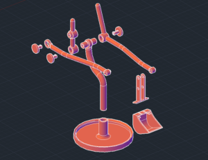
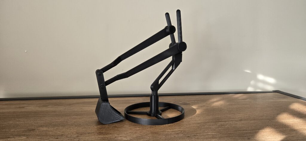
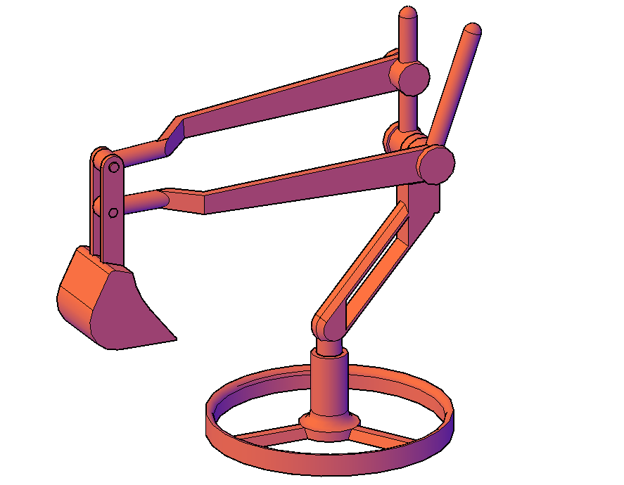
The Complete Design
Finally, after initializing, refining, and making several tweaks, the overall design is now complete. This process came a long way from Version 1 and Version 2, but that road led to a functional and aesthetic Version 3.
If you like what you have seen and want to 3D print the excavator for yourself, you can download the files from here.
The excavator is complete for now, but I do have some ideas for it in the future. I mentioned in Version 2 that it’s current design has modular functionality, so expect to see it again in the future with a new look. Thank you for following along!