Part 1 – 3D model features in Version 1
The best things about 3D printing is that it lets you build anything you want. You can even recreate childhood play-ground fun in a desk-sized project. One such form of inspiration comes from the sand excavator commonly found on playgrounds, which kids sit upon to scoop sand. I wanted to have one of these excavators at my desk, so I went ahead to design one for myself. While the mechanisms involved are intuitively simple, applying all elements correctly requires careful consideration of geometry, material properties, constructability, and the intended functionality of the design. Here’ we will follow the design process for Version 1. You can follow the next iterations of the excavator at Version 2 and Version 3.
Designing the Mini Excavator in 3D
Accommodating for balance and stability
In the first part of the design I begin to think about how the excavator will swivel and how will it remain balanced. The ones you see in playgrounds consist of a swivel bar extending into the ground. This swivel bar provides both the movement and the structural stability. The desk toy, in comparison, is only capable of resting on a surface. This lacks the structural support that the life sized version has. The first attempt to remedy this is to provide a wider base to swivel upon.
The full-size playground excavator achieves stability mainly through the embedded length of the rotation rod. The relative positioning of the control levers and the passenger will also play an important role. While the exact design varies, the levers are placed around the pivot point, with the passenger’s seat positioned behind it. This configuration allows the operator’s weight to contribute to balancing the mechanism during use.
In contrast, the 3D model incorporates design changes to better suit desktop operation. The control levers are positioned further behind the pivot point for two main reasons. First, without an operator’s weight to counterbalance the system, this offset helps shift the center of gravity closer to the center of the base. Second, the extended positioning creates a horizontal lever, making it easier for the operator to swing the shovel.
Arm Geometry
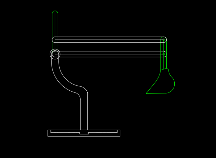
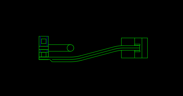
The next step involves fine-tuning the arm geometry to achieve the desired lever action. I begin determining the degree of motion of the shovel that I wanted to see against the rotation base. As the position of the shovel is adjusted, I then determine where the levers should be angled. As shown, the levers will be pointing up perpendicularly from the ground when the arms are positioned parallel with the ground.
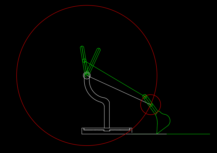
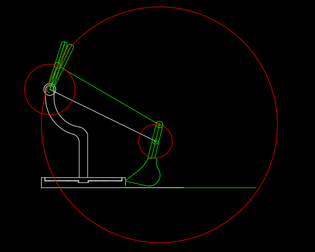
A circle is drawn at each movement point to show the full range of motion for each components connection. This helps illustrate how all the moving parts work together. Now, we can see how the shovel will act based on the inputs provided by the levers. From here, the lengths of all parts and point locations are adjusted until the geometry allow for the best operation.
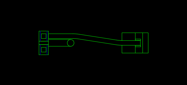
The photos above present the more complicated features of the arm geometry. To further illustrate this design, a plan view reveals additional details of the arm geometry. The levers are positioned side by side for smooth operation. The shovel is then positioned in between the levers and centered with the excavator rotation rod/swivel post. Joining the levers to the hinge points on the shovel requires a bend in each arm to meet at the shovels center. Now, moving forward with this concept brings considerations on how the arms will be connected to the shovel. We will go into more detail in the next section.
The process for developing the are geometry required continuous refinement and iteration. While design requirements have been determined, they aren’t problems that are solved one at a time, but are all factors that must be considered simultaneously. Even the smallest change to one component affected the overall geometry and performance of the system. It serves as a constant reminder that, the intuitive understanding of how a mechanism works can be deceiving. The precise positioning, dimensions, and geometry demand careful scrutiny during the design process to ensure the system operates exactly as intended.
Constructability of parts – Strength and integrity for 3D Printing
The geometry has now been finalized and verified to function as intended. The next step is to develop a method for assembling all components. When creating an assembly strategy, several factors must be considered, including rotational tolerances, clearance or interference fits, and part thickness. Since this project is designed for 3D printing, additional considerations such as print orientation and material efficiency also influence the design. Decisions about whether components should remain as a single piece or be divided into multiple assembled parts played a significant role in determining print layer direction to ensure adequate structural strength.
I attempted a few tolerance fit tests that were first incorporated into the design. The rule that worked for me was the following; loose fits that allowed movement: 0.2mm clearance around each edge. For tight fits: 0.1mm clearance around each edge.
The excavator arms needed a way to connect to the shovel end while also connecting to the swivel post with free movement. With this first version of the excavator, I aimed to make an easy, fully assemblable design. To adapt this philosophy at the shovel connection, I designed the arms to fit in between two plates extending out from the shovel. These two plates will fit snug on the outside of the arm end points where the holes will align and connect. Rods and end rivets were then designed to fit through the holes of both the shovel plates and end of the arms.
At the other end of the arms, they will meet up with the connections that are incorporated as a part of the swivel post. At the top of the swivel post, two cylindrical shafts extend outward, allowing the built-in bearings of the arms and lever components to fit over them and rotate freely. To keep the arm and lever component from falling off from the shafts, separate plugs that fit over as a stopper fits into the end of the shafts with a tight fit. The same type of plug is used in fastening the other arm into the lever component.
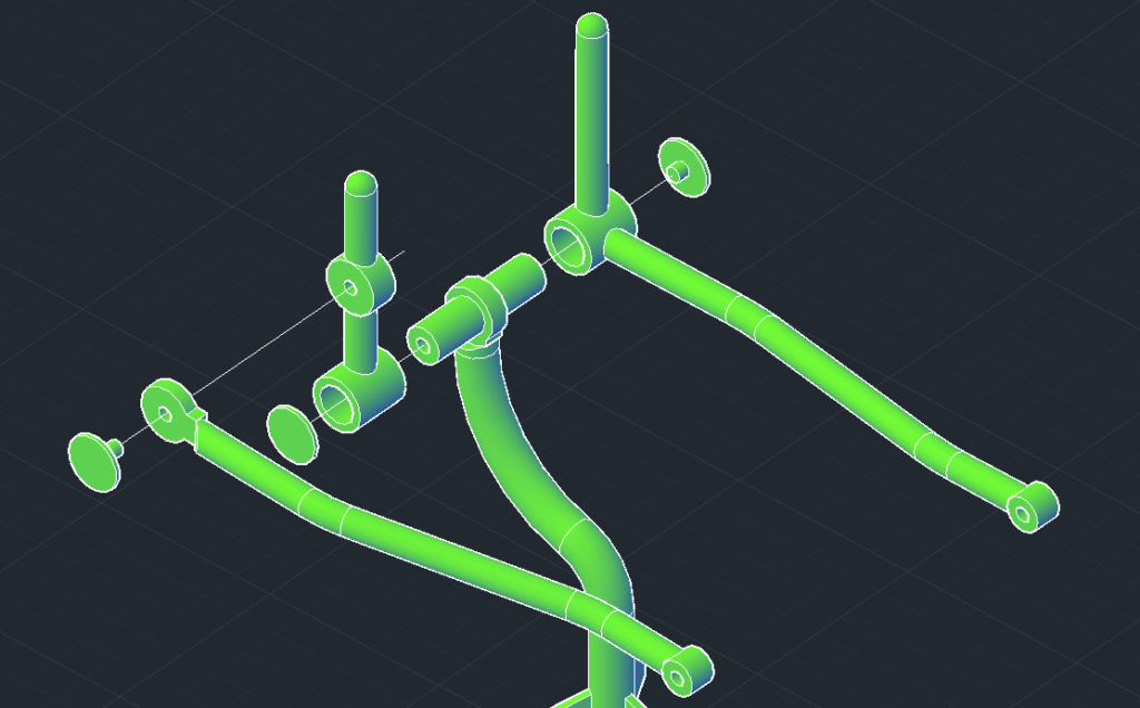
Near the base of the shaft, at the swivel point, the end of the post uses trapezoidal plates to help secure it to a wide circular base plate. This circular plate then fits into a stationary plate with a raised rim around its circumference, which retains the base plate in position while allowing rotation.
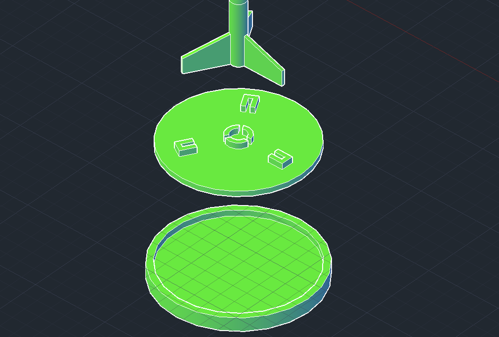
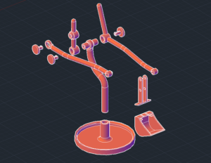
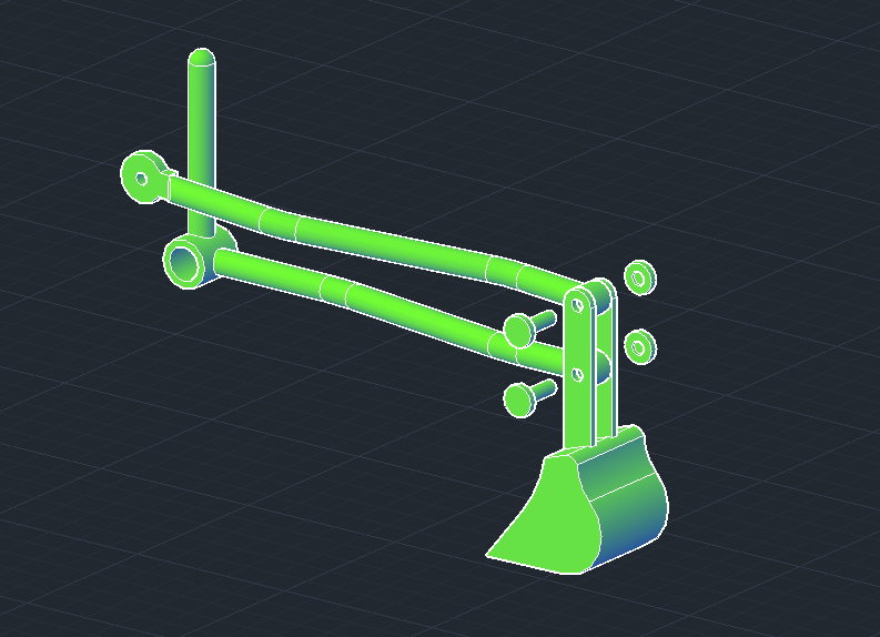
As we modeled the components, we integrated considerations for efficient and practical 3D printing into the design process. We designed each piece to lie flat whenever possible to minimize wasted filament. We also focused on ensuring structural strength where it was most needed. For example, we oriented the arm bearings on the print bed so their full circular profiles could be printed layer by layer, rather than stacking the layers along the length of the bearings. This orientation also helps run the print lines along the length of the arm, providing resilience against a vertical load.
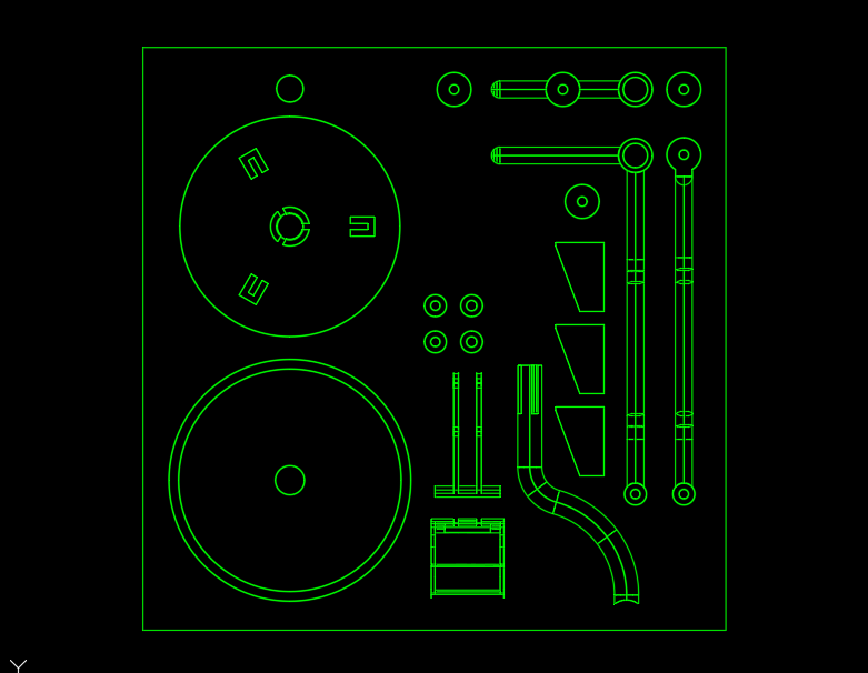
The image shown illustrates the orientation of all components according to optimal print-bed positioning. This configuration is intentional, as it maximizes structural strength while minimizing filament usage.
Testing the first 3D Print
While the design decisions appear logical, the most effective way to verify proper functionality is through physical testing. Printing the model will help determine its performance and evaluate any flaws.
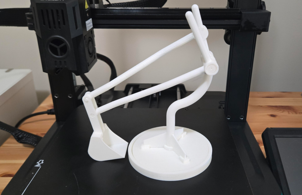
After the print and assembly, the whole thing came together without much difficulty. However, there were areas of improvement that made themselves known with further inspection. Lets list out some of he biggest pros and cons that cam out of this design:
Pros:
Arm geometry: The arm geometry works magnificently. The intended lever movement tied to the desired shovel movement functions the way it was designed and requires very little to no modifications.
Loose fit tolerances: The tolerances used at the arm joints and swivel base allowed for smooth, free movement.
Cons:
Tight fit pieces: The snug-fitting components, such as rivets securing the arms and shovel, are difficult to assemble. Even with ideal tolerances, consistent fit across different 3D printers cannot be guaranteed. This will continued to be worked on towards a better solution.
Swivel base: Slightly too much force is required to swivel the excavator into position, which can cause the entire model to be pushed aside when only rotation is intended. This issue is primarily due to excessive contact area between the two circular base components. A revised design will be attempted to reduce the force needed to rotate the excavator on its base.
Trapezoidal plates:
The plates intended to attach and support the post to the base were partially effective but had flaws. The tight fits made the structure difficult to assemble and prone to separating under applied force. The design was also overly complex and overengineered for the forces encountered during use. Now seeing the redundancy of these overdesigned plates, a simpler design will be attempted.
The results of the first print revealed both successes and areas that require more attention. While there are still improvements required, this first print can be considered a success. The overall intention of the design has been met and does not require an entire redesign from scratch. In part two of this project, we will go over the next phase of refining the design and how the arisen problems will be solved.
Conclusion
While this marks as a good first start towards completing this mechanism, there are still some problems that require more attention. Check out how these solutions will be solved in part 2.