Beginning with the Gear Box
Taking on a large-scale project can feel overwhelming at first, but breaking it into smaller parts makes more manageable. By identifying the core systems within the project, you can focus on solving one piece at a time instead of handling everything at once. Here, the starting point was defining two key elements: the input action and the intended output of the final mechanism. From there, the design moved through several conceptual phases and iterations until I arrived at something that worked—at least on paper. Of course, a design functioning in theory doesn’t guarantee success in practice. Once translated into a physical prototype, the system quickly exposed flaws that weren’t obvious during the planning stage.
Rather than attempting to troubleshoot every issue across the entire design simultaneously, I divided the project into its main systems and focused on refining them individually. The first of these systems is a relatively simple gearbox. With only three moving parts, its motion is straightforward and easy to visualize. However, the geometric considerations behind each component are far more intricate than they initially appear. In the following section, I’ll break down the elements of the gearbox and explain how they work together.
If you are interested in seeing other similar projects, you can find one here.
Design Intentions and Requirements
The indented transfer of motion for this design starts by inputting a rotational motion by means of a crank along the x-axis. The gearbox translates that motion into rotation about the y-axis, producing one full output rotation for every two rotations at the input. To achieve its intended function, I carefully scrutinized each component, refining the details so they would work together seamlessly. The following are all components involved for the gear box:
- Bevel gears (45 degree gears)
- Worm gear
- worm wheel
- Key holes
- shafts
- Support structure
Each of the listed components will be thoroughly described in detail, provided as a basic ‘how to’ guide for anyone wanting to design similar components for themselves.
Bevel Gears
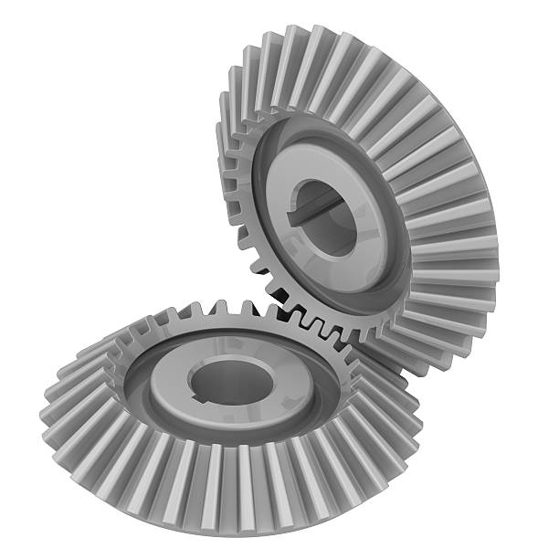
Bevel gears are a type of gear that transmits power between intersecting shafts. The shafts can vary in the angle at which they intersect each other, but most commonly intersect at 90 degree angles. Conversely, gears that work in parallel shafts are called spur gears. To begin designing for the bevel gear, I determined the number of teeth and tooth ratio that both gears will require.
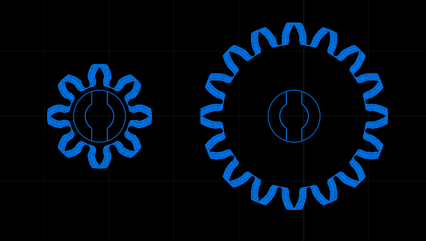
The gear ratio intended for the meshing bevel gears is set to be 1:2. This means that for one rotation of the input gear, the output gear will result in 2 rotations. In other words, the input gear will require twice as many teeth as the output gear will. To quickly refine the gear design, we input the tooth count into a spur gear generator. This application uses the following gear generator.
We evaluated multiple tooth count combinations while maintaining the required gear ratio. After iterating through these options, we selected 16 teeth for the input gear and 8 teeth for the output gear. The minimum number of teeth required on the output gear to ensure smooth operation primarily drove this decision. The lower tooth count allows for smaller diameters and less filament usage to print the gears. This also achieves a higher gear ratio while minimizing spatial requirements.
When making a gear’s with a smaller tooth count, we need to consider both the advantages and drawbacks.
Advantages
- Compact gear designs that make it easier to fit in a smaller space.
- Less filament use when 3D printing
Disadvantages
- Enhanced wear of the teeth, since each tooth is engaging more often that they would with a larger tooth count.
- Each tooth is larger but fewer teeth share the load.
- Greater chance of slippage and a lower contact ratio. This can increase noise and vibration in the system and exacerbates tolerance stack-up issues (which will be discussed more later).
Choosing a tooth count any lower than 8 isn’t ideal. For example, reducing the tooth size down to 6 teeth would introduce a higher possibility for issues to occur. Reducing teeth from 8 to 6 removes 25% of the total teeth that interacts with the meshing gear, greatly enhancing the listed disadvantages. Compared to, say, reducing a 30 tooth gear to 28 teeth, reducing it’s amount of teeth by about 7%. We deemed 8 teeth for the smallest gear to be a good sweet spot.
The next step is to convert the spur gear templates into a bevel gear (45 degree) application. Traditional bevel gears, called straight bevel gears, angle the teeth rim so they mesh at the required angle.
The approach to designing the bevel gears for the gear box are a bit different. Rather than angling the teeth to mesh, the teeth lie flat relative to the gear face, but they introduce a pronounced pitch angle at their cross section.
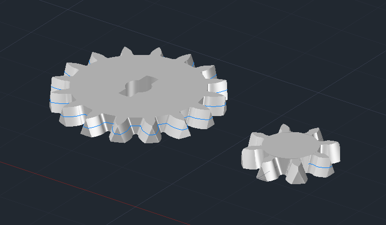
This approach is preferred for two reasons. It makes the gear easier to design and it makes them easier to print in filament. An excellent guide to designing this style of 45 degree gears can be viewed here.
Flat Bevel Gear Design Guidelines
For a quick summary, these style of bevel gears work best when balancing a few factors. The primary considerations include the gear’s thickness, the tooth angled cross section, and basing the design on a spur gear profile taken at the midpoint of the gear’s thickness.
First, establish the spur gear profile that will define the bevel gear geometry. Then determine the gear’s pressure angle, which controls how force transfers between meshing teeth. In other terms, the pressure angle is the line of action (the line along which the contact force acts), and the tangent to the pitch circle at the point of contact.
Pressure angles are typically standardized at 20°, although 14.5° and 25° are also common. The spur gear template used in this design has a 20° pressure angle. To adapt flat spur gears for bevel gear operation, apply the pressure angle to each tooth’s cross section. This modification allows the gears to mesh perpendicularly to each other. Think of it this way: if the pressure angle enables two gears to mesh smoothly in one plane, applying that same angle to the tooth’s cross section creates an additional plane for the teeth to engage with.
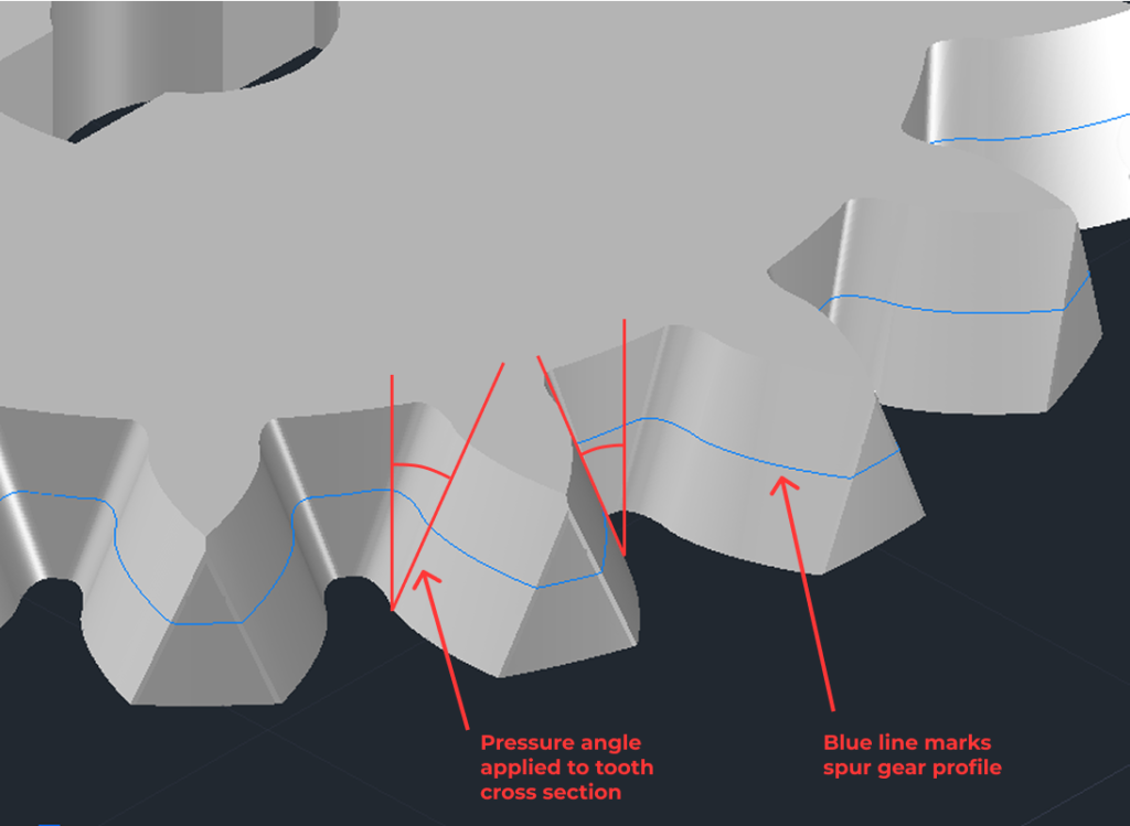
The gear thickness affects how strongly the pressure angle is applied to each tooth. Making the gear thicker results in a narrower tooth width at the top, since the pressure angle extends further toward the top of the gear from its base. For applications like this, adjust the gear thickness so the outer surface of the tooth doesn’t intersect into the top edge of the gear tooth. The one I made intersects slightly into the top edge, resulting in a newly formed crest at the top corner of the tooth. It still works well, but this crest should not be prominent in the gears geometry.
Completed Bevel Gears
text
Worm Gear and Worm Wheel
Worm gears help transfer motion between two shafts that are at 90 degree angles to each other. Before beginning the worm gear design, I had to determine some design guide lines:
- Revolutions of the worm gear shaft connected to the smaller bevel gear
- Output revolutions of the worm wheel meshing with the worm gear
- Profile of the worm wheel
- Transmitting revolutions of the worm gear to the worm wheel
Input and Output Rotations
At this stage it is necessary to verify how the output of the system will react compared to the input of the system. The input rotation of the large bevel gear transmits rotation into the small bevel gear. The small bevel gear is connected to a shaft that also connects with the worm gear. Finally, the worm gear transmits rotation to the worm wheel, which is the output.
The rotational relationship I want between the input and output is that the output completes one rotation for every two rotations of the input. One rotation of the large bevel gear already transmits into two rotations for the small bevel gear. You might wonder why the bevel gears increase the rotational speed from the larger gear to the smaller gear when the goal is for the system’s final output to rotate at half the speed of the input. This is to accommodate the restrictions of a worm gears axial pitch and lead angle.
Designing the Worm Gear
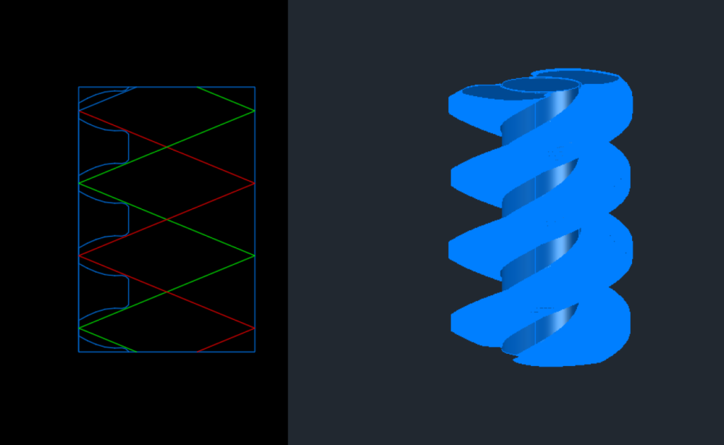
The worm gear needs to accommodate meshing, pressure angles and other design variables for it to function as intended. Since those design variables were verified in the bevel gear design, I went forward with using these same variables for the worm gear. The concept here is to take a single tooth of the bevel gear and wrap it around a helix.
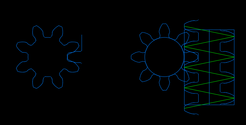
I adapted the worm wheel profile from the same 8-tooth spur gear used in the bevel gear design. Since this tooth forms the worm wheel, using the tooth profile already designed to mesh with it ensures proper functionality. The green line in the image represents the path that the tooth takes to wraps around the shaft.
The worm gear is currently designed so that the tooth cross-section rises by one tooth span (axial pitch) for each rotation. This makes it so that each rotation of the worm gear will push a single tooth of the worm wheel by one axial pitch. In other words, one rotation of the worm gear equates to 1/8 of a rotation for the worm wheel. To speed the rotation of the worm wheel up to the required 1/2 rotation, additional helices can be added to the worm gear.
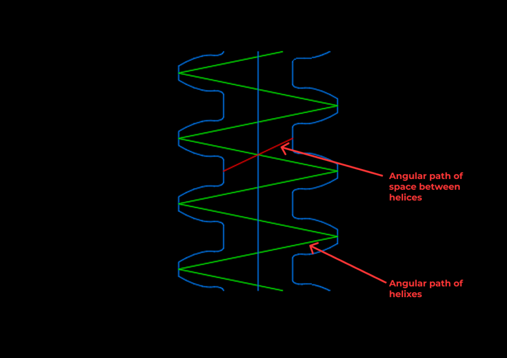
This change to the helixes can be slightly deceiving. To achieve with only worm gear modifications, the axial pitch of the worm gear will have to quadruple in length. This change would make the axial pitch almost the entire length of the worm gear and make the lead angle too steep to engage with the teeth of a worm wheel.
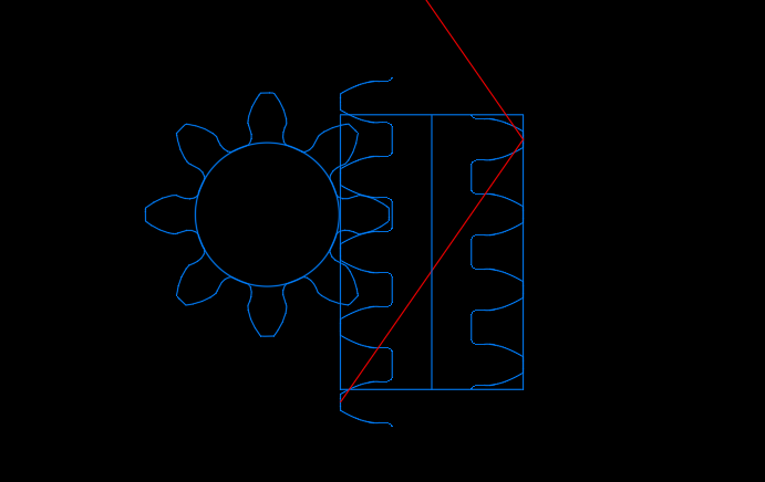
The solution for the final worm gear build is to comprise it of two helices. The design ensures that each rotation of the worm gear causes the worm wheel to rotate by 1/4 of a turn. The bevel gear system provides the remaining 1/4 of the required rotation by doubling the speed through its 2:1 tooth ratio.
Completed Worm Gear
To account for the difference between the input and output rotation ratios, the worm gear rotates the worm wheel 1/4 of a rotation for each rotation of the worm wheel. The bevel gear system takes care of the other 1/4 rotation.
Designing the Worm Wheel
The worm gear already defines the profile of the worm wheel. The next step is to ensure that the wheel meshes properly with the worm gear helices. Simply extruding (extending a 2D shape into the third dimension to create a 3D object) the gear profile into a solid shape will not achieve this; the profile must also twist slightly as it extrudes so that it aligns with the worm gear. The required twist angle can be determined by examining the worm gear cross-section.
When I first designed the worm wheel, I thought the extrusion should twist along the open path between the helical teeth. Since the worm wheel fits into the gaps between the teeth, it seemed logical that it should follow that path. However, this assumption was incorrect. The extrusion must instead twist to match the path of the helices. The thought process behind this is to think of the teeth/helices as the driving factor that will transmit rotation from the worm gear to the worm wheel. For this motion to transfer effectively, the worm wheel must match the geometry of the teeth that drive it.
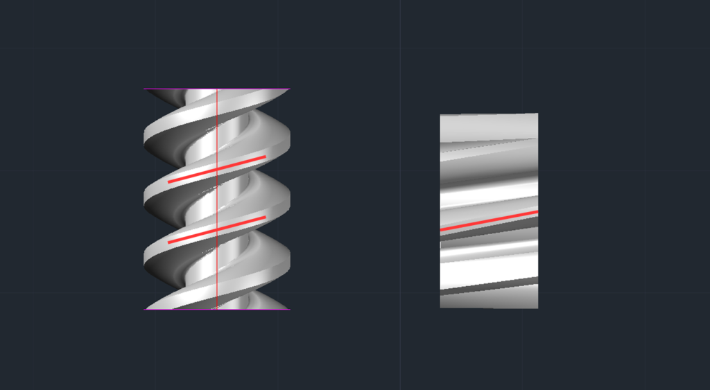
With the worm wheel extruded at the correct angular path, it fits properly into the worm gear.
Key Holes and Shafts
Gears are connected to shafts using a key, which is a straightforward rectangular piece of metal that fits into matching slots in both the gear and the shaft. The purpose of the key is to stop the gear from rotating separately from the shaft, ensuring they turn together at the same speed. The key is designed to break if the gear experiences forces beyond its limits, helping protect both the gear and the shaft. This gearbox design uses a different approach to applying the keys.
Key hole
An outline of a non circular hole pierces though the center of the bevel gears and worm wheel. The hole’s outline consists of a circular shape with rectangular sections on opposite sides, positioned 180 degrees apart. Although the shape is symmetrical, it prevents a shaft with a matching profile from rotating freely.
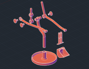
Shaft
This design integrates the keys directly into the shaft, reducing the number of separate parts and forming it into a single piece. This avoids the difficulty of trying to fit a small 3D-printed piece into a separate key slot. As shown, the profile of the built-in keys matches the keyways in each of the gears. The gearbox is designed with two shafts to function. Each shaft includes built-in shoulders and journals (section of the shaft that fits into a bearing or hole) to provide adequate support locations, which support is provided by the housing of the gear box.
To simplify the design, we integrate the worm gear directly into one of the shafts.
Support Structure
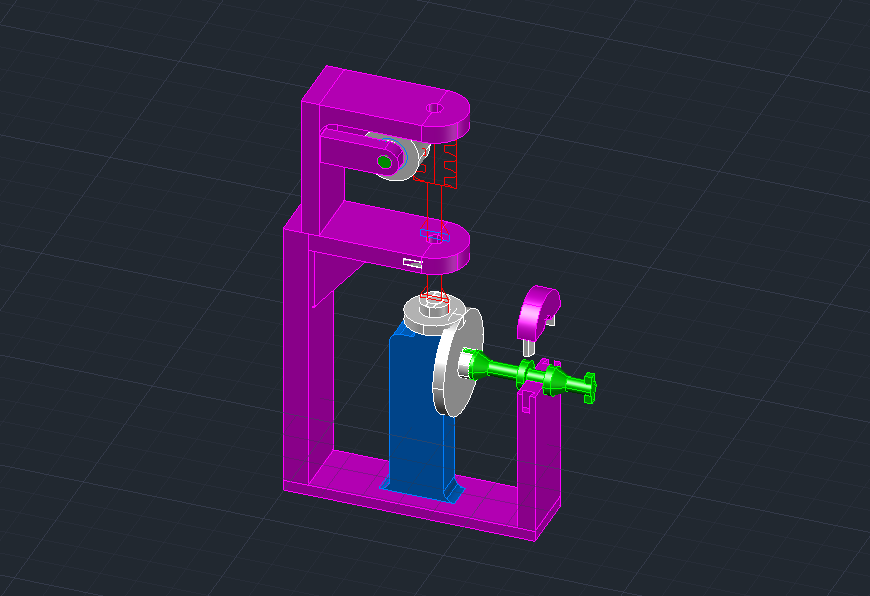
Supports built into the gear box serves more than as a means to hold the components in place. They also keep proper positioning of components relative to each other for proper functionality. The gears can only engage as designed if they stay positioned at specific spans from each other. To reflect these spans in the structure, we begin by positioning the components in the 3D model to ensure for proper alignment and meshing.
We add structural components to secure the parts. We treat this phase as a functional test, prioritizing proper operation before refining the design for ease of 3D printing.
The support does not look pretty, but at the physical test, all gears meshed quite easily with only minor adjustments required. A hurdle which requires more thought prior to finalizing the structure is, again, tolerances. Specifically, spacing required between the shafts and their support locations. Enough space needs to be allowed between the shafts and their supports to allow for free rotation. But providing too much space between these spots introduces a problem that can easily halt operation if overlooked, tolerance stack-up.
The Problem of Tolerance Stack-up
Tolerance stack-up is a factor in any manufactured part where the combined effect of individual feature tolerances influences the final result. It can also impact how components fit together, since small dimensional variations in each part may accumulate during assembly. Every manufactured part includes a tolerance, which is a permitted variation from its exact dimension since perfect precision isn’t achievable. When multiple parts are assembled, these variations can accumulate and negatively influence the final outcome.
A 3D-printed project requires more careful consideration of tolerance stack-up than parts made with traditional fabrication methods. For example, machining metal allows manufacturers to achieve highly precise dimensions, while 3D printing builds parts by melting filament and depositing it layer by layer. This process introduces more variability due to factors like print speed, thermal expansion and shrinkage, and limits on filament thickness. These variables can change from one print to another, so even identical designs potentially produces different results.
To accommodate for these factors, designing 3D printed parts to fit together may require looser tolerances. And once you incorporate looser tolerances, tolerance stack-up invites itself into the fray. The bevel gears and shafts rely on a reasonable alignment for them to mesh properly, but misalignment from tolerances can make the whole contraption seize up.
Minimizing Tolerance Stack-up
Designing the structure requires actively minimizing tolerance stack-up from the start. This will be achieved by splitting the structure into as minimal pieces to print as possible. Alternatively, the structure would be split into multiple pieces, then assembled after printing. The problem with multiple pieces is that when more of these pieces connect, each connection has a variance in its tolerance. Thus, the more connections you introduce, the more points of varying tolerance you introduce into the system.
My first solution fixes the frame so the worm wheel and worm gear mesh in a set position. Printing the frame here as a single piece prevents tolerance misalignment between these gears. The two ends of the worm shaft act as ‘pivot points’ that can move slightly. The bevel gears are isolated from the ‘worm system’ in it’s own fixed frame, bypassing a tolerance misalignment for the two gears to mesh at 45 degrees.
Both of these fixed frames slide into place to allow the ‘worm system, and the ‘gear system’ to interact with each other. This introduces one point of structural tolerance in this connection. The tolerance in that connection is manageable and a reasonable trade off for easier 3D printing. The main goal is to minimize as many structural connections as possible.
this structure serves as a proof of concept at this stage. The next step is to take these concepts and implement them into the next iteration of the project: using the worm wheel to complete a task.
Next Steps for this project
With a working gear prototype complete, the next phase adds new components to the mechanism and transfers the worm gear’s motion to another component.