To become proficient in design, one must practice and incorporate various techniques into their workflow. While some of these techniques may be more apparent, others may be less obvious, even though they are frequently used. One of these regularly used but overlooked practices is geometry, which is defined as ‘the branch of mathematics concerned with the shape of individual objects, spatial relationships among various objects, and the properties of surrounding space’. The mathematics of geometry can be taken to far extents of precision and understanding, but for the purposes of designers, much of these mathematics can be bypassed with several drafting techniques, which can pull information from a drawing that would take more effort to calculate and arrive to the same value. In order to develop proper drawings for any given component or designed area, the designer must first have a proper understanding of the object in 3D and understand how to logically present all of its features with various 2D images. The specific branch of geometry that allows the representation of three-dimensional objects in two dimensions by using a specific set of procedures is referred to as descriptive geometry. To explain this a bit better, lets first begin by referencing to a design drawing.
Constructing New Views
Geometric techniques are consistently employed when creating the views in a design drawing, even when it seems simple enough not to be apparent. One of the most common ways that geometry is utilized is in comparing different views of an object, along with dimensions, to reveal other information about the given object. To explain this concept, we will use a simple part drawing provided by ‘Clemson university’.
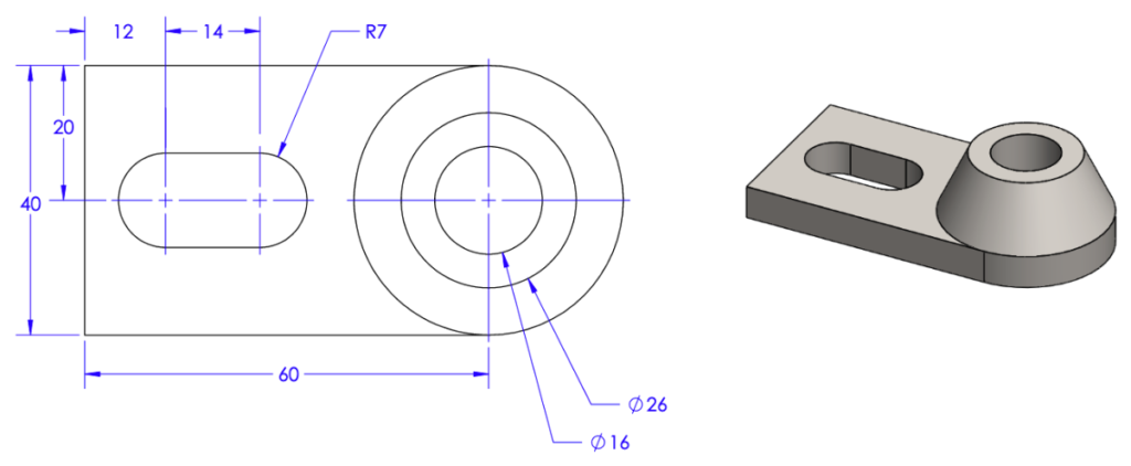
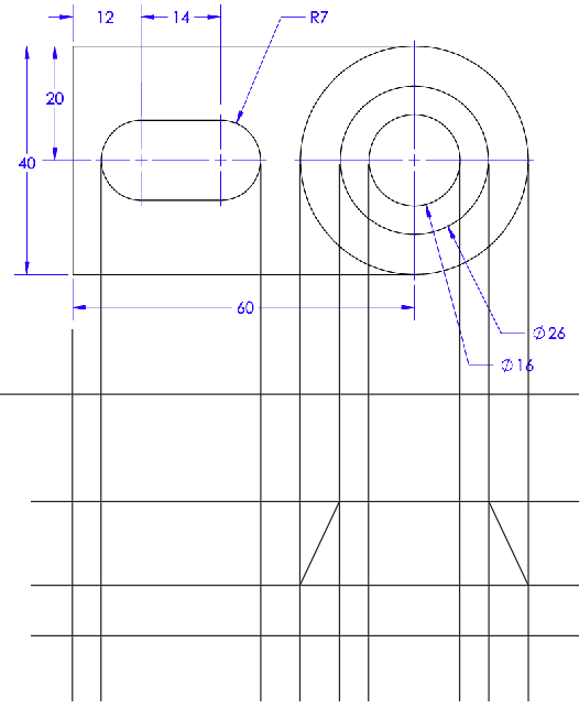
To begin, we are provided an isometric view of the part (right) and a top view of the object, with dimensions of its features (left). From here, lets say that we were given two other dimensions of this object, the total height being 23, and the height of the base being 8, and then asked to provide a drawing of the front view of the object. First, by observing that the total length of the object is provided, which will not change, much of the required info for this new view can be provided by extending reference lines down form the top view.
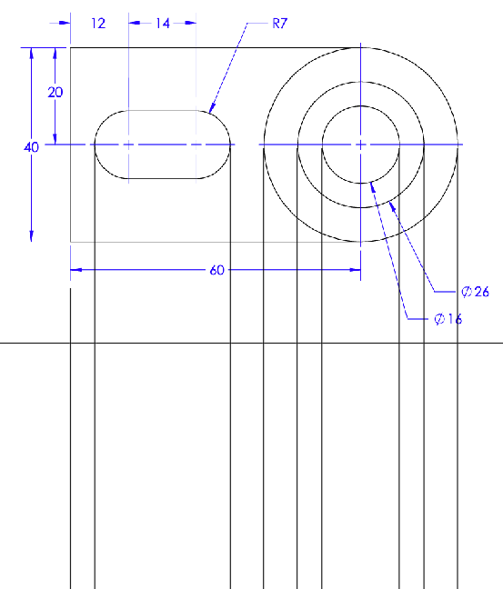
Next, we know what the heights of the respective pieces are for the object. The isometric view also shows the relationship of the flat planes with the cone shape of the object. We can combine that information to draw more lines to get us closer to completing the view.
To finish off the view, the lines will be trimmed back to reveal the outline and hidden lines of the object.
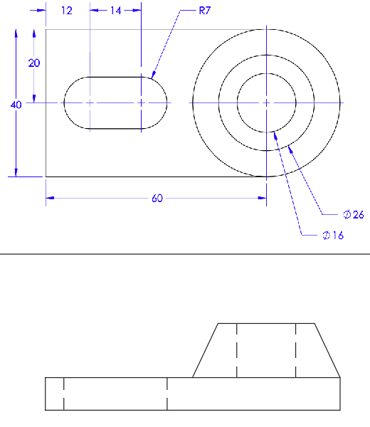
Now lets refer to the original drawing and see how the view looks with dimensions provided.
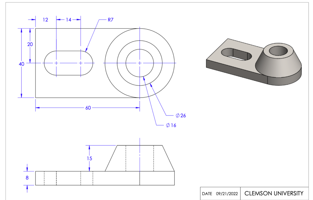
Now, with the information provided here, the part could be recreated in 3D is desired. The views that are provided on the completed drawing can also be used to create a view of the side of the object by utilizing the same techniques for developing the front view without require any other dimensional information. This is a simplified example, but it demonstrates how understanding the relationships between an object and the properties of the surrounding space can be used to create a full view of the object, thus, being an important application of descriptive geometry.
Using Geometry to Fill in the Gaps
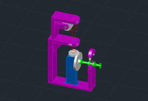
Now lets being reviewing a more complicated example. Here in this drawing, we see that the object has more complicated geometry in other views than from the previous object. The reason why this drawing requires three views rather than two is because the shape of the object is unsymmetrical along its side view (bottom left), requiring this detailed view to show how all the shapes interact with the other shapes to construct this side. The way the views are lines up in relation to each other is also important in this drawing. Just like as practiced in the last example, if you draw lines of the edge of the object from one view to the next, you will see that they line up.
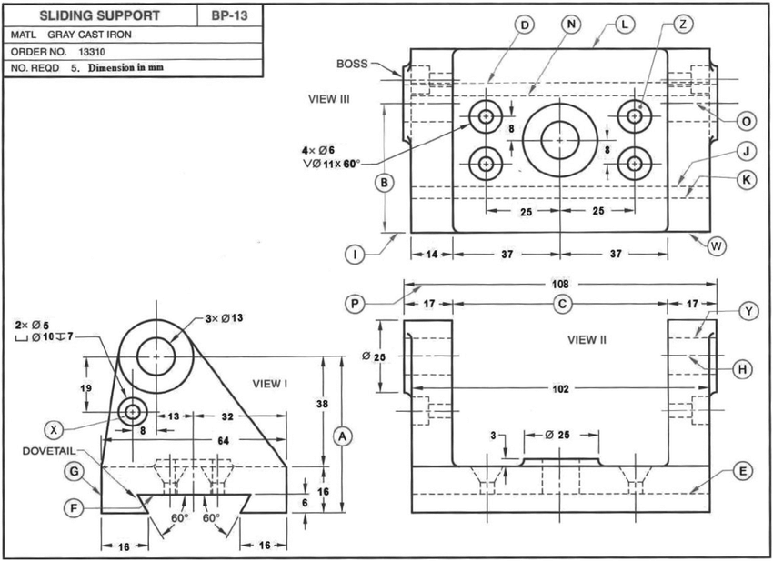
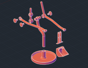
From reviewing the dimensions provided on the drawing, an isometric drawing can be developed if required. Drafting an isometric drawing with 2D lines requires some inspection, but it can be done with descriptive drafting techniques, by translating construction lines along a given angle. You will also notice that not every single line or object is provided with dimensional information, which is actually not necessary, since by using certain practices we can connect lines from point to point at confirmed corners in order to draw a line in place. For example, the top circle has a tangent line touching the outer circumference and then drawn in straight to meet the top corner of the object base.
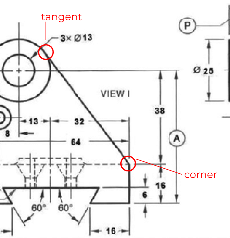
Similarly, the slot at the bottom of the base is only provided with the angle and the height of the slot. This is the only required information to produce the shape in this view, as the angle combined with the height is enough to provide the corners, in which a line can simply be drawn in between. This style of drafting, without providing every single dimension, is the common practice by presenting only the limited amount of information required to generate a shape, where as geometry can be used to fill in the missing gaps.
There are situations in design where the length of these missing dimensions are required. A simple way to find the lengths of these missing dimensions, with access to the drawings, would be to directly measure along the line. Provided that all views are correctly scaled relative to one another (which is standard practice), you can use a ruler to measure any span on the drawing and obtain the correct dimension. When drawings are made to scale using descriptive geometry techniques, you can extract any needed dimension, making these drawings highly valuable. As you can see in the said example, we will measure length of a line on the drawing that isn’t explicitly given, and see what the value comes out to.
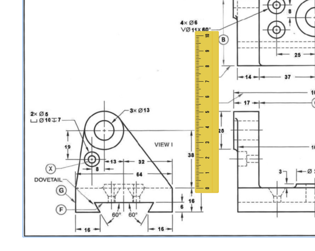
We’ll start off by scaling the image of the ruler and the object in relation to each other so that each unit equals one millimeter on the ruler.
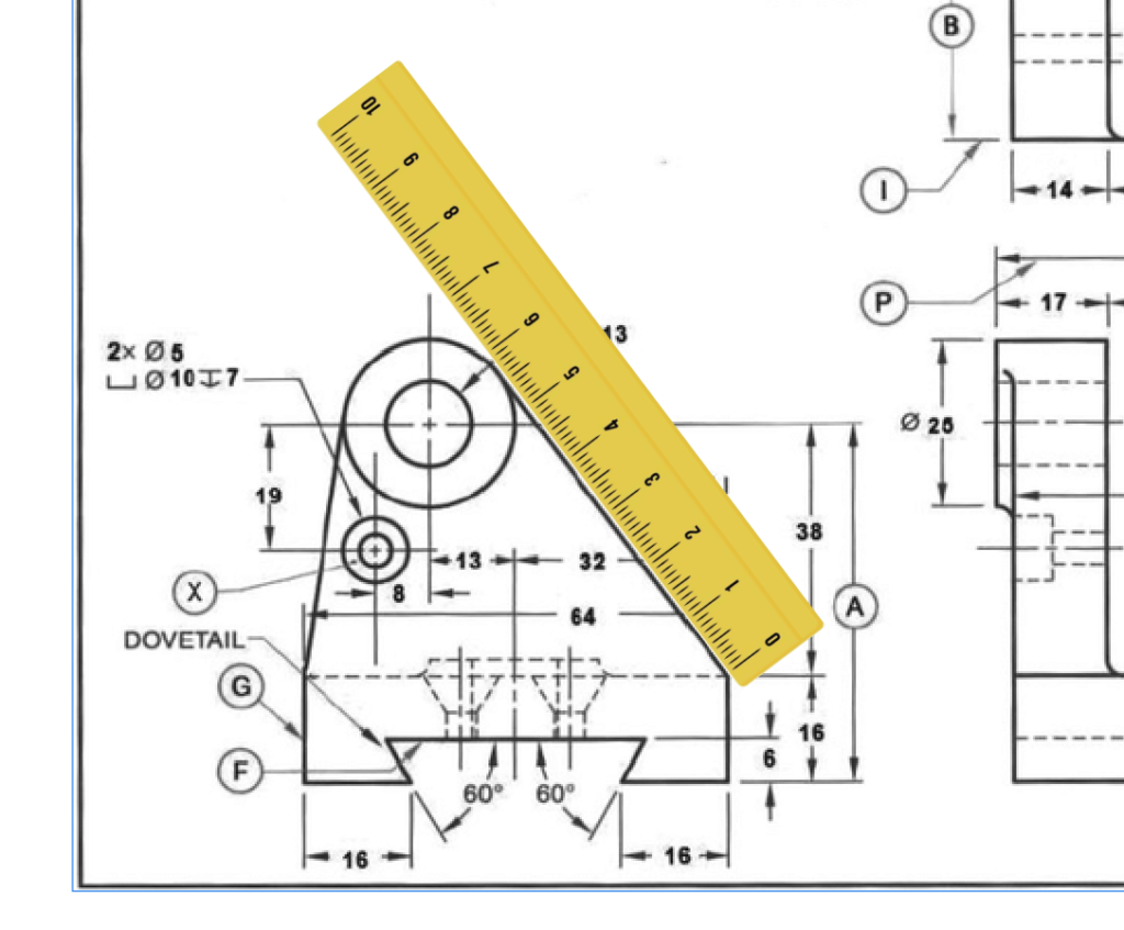
Next, I’ll position the ruler to line up along an edge that doesn’t have a length provided. In this image, I angled the ruler so that 0 starts at the shown corner, since this is a tangible point that is easy to position the ruler against. Judging from where the other end of the line ends, tangent with the circle, the rough measurement of the line looks to be in between 57 and 58 millimeters. Now to verify this length lets compare it with this dimension taken form an AutoCAD model that I made from the information given in the drawing.
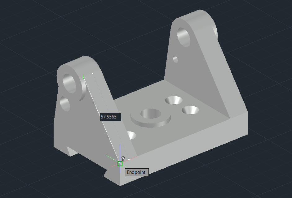
As shown, the total length of this edge measures 57.5565 millimeters. While using a ruler to measure an object from a drawing is limited by how precisely we can align the ruler with the line, it still provides a reasonably accurate measurement when it’s the only method available. This, along with similar situations, highlights the value of descriptive geometry—it offers accurate visual representations of objects, allowing you to extract reasonable accurate information as long as the proportions are maintained.
As regular as these techniques are in generating design drawings necessary for many industries, I often hear from regularly practiced designers from how these practices can get overlooked. I have even heard from designers before that they haven’t practiced anything geometry related since they were in school. This is not all that accurate since geometry is an essential part of a designers tool set, and necessary to produce anything with some semblance of accuracy. It tends to get overlooked because the simpler techniques are so regularly used that they become commonplace in developing drawings.
Conclusion
Descriptive geometry is a crucial branch of geometry that helps to logically depict the relationships between features of an object and represent them accurately in a 2D visual format. This is just the beginning of exploring the often-overlooked applications of descriptive geometry, which can also be applied in more complex contexts to uncover information that might not be immediately apparent without geometric analysis. If you’re interested in learning more about this topic and would like a deeper discussion, feel free to comment and let us know!