Part 2 – Refinements made for Version 2
Design refinements during the mid stages of a project are a natural and necessary step in advancing toward the final, fully functional outcome. In part 1, we covered the process of designing and completing the first print of the excavator, referred to as Version 1. Although several aspects of the excavator functioned as expected, other areas revealed the need for improvement. Each of these areas will be discussed to identify the issue and explain the solution implemented. as a result, hopefully someone may find use and implement any of these findings into their own projects.
Before moving on, you can find a detailed description of the problems in Version 1. Here is a brief summary of the issues we will tackle: Tight fit tolerances, making a better base for swiveling, adjustments for levers, making loose fit rivets, and a brief design into hinges.
Tight fit Tolerances
I found it easier to design components with looser tolerances compared to those requiring tight tolerances. Loose tolerances allow for a wider range of fit between pieces before the gap becomes excessive. In contrast, tight-fit tolerances offer a much smaller margin where parts can fit together before excessive force is required.
In 3D printing applications, tight tolerances can become especially problematic if insufficient attention is given to the placement of the z-seam, particularly when it falls within a tight-fit area. The z-seam overlaps two ends of a print layer and often creates a small bump on the surface, which can disrupt pre-designed tolerances and interfere with part assembly. For this reason, areas that were originally designed with tight-fit connections were redesigned to accommodate looser, more forgiving fits.
Swivel base
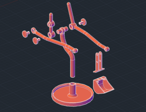
In version 1, the post of the excavator connected into a wide circular plate using three additional trapezoidal plates that would all connect together with tight fits. The circular plate would loosely rest inside a wider base, giving it free range of rotation.
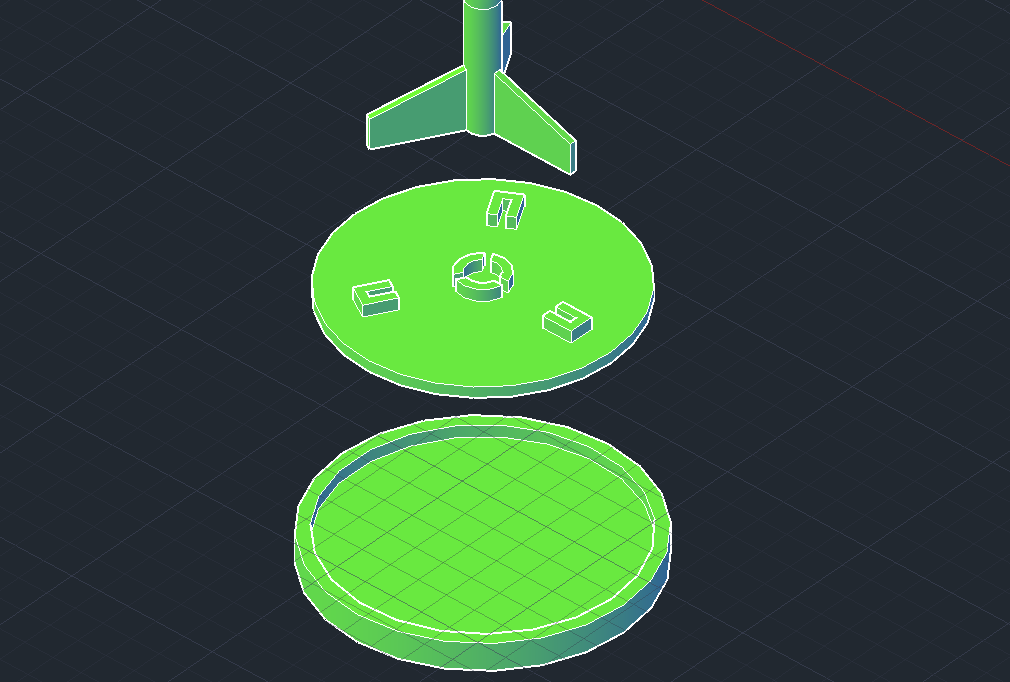
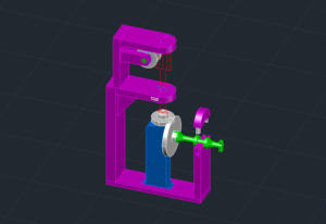
While loosely taking inspiration for a wider base from turrets, the application for the excavator presented issues. Rotating the excavator required too much force, which was a result of too much contact area between the circular plate and base. This often caused the whole piece to shift over when a force intended for rotating the excavator was applied. The tight-fit connection plates and method for swiveling were eliminated and replaced with a simpler base concept. Inspiration for this new design came from the swivel mechanism used in stationary jib cranes.
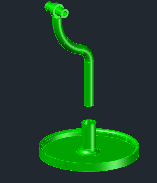
Here, the post of the excavator fits into an extruded cylinder from the base. This application works much better than the former design. It is simpler to print, reduces filament while requiring less pieces to make it work.
Arm Levers
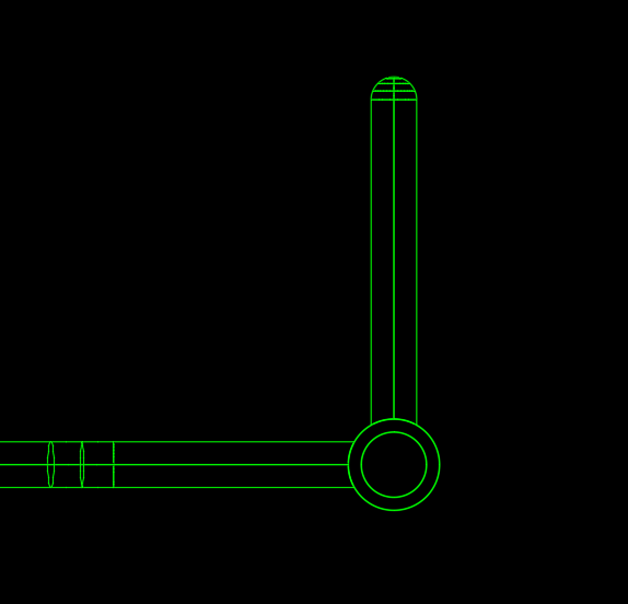
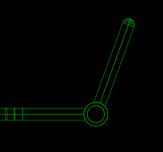
To further help with rotating the excavator I decided to rotate the fixed lever handle for the left arm. By rotating the handle by 15 degrees around it’s pivot point, the arm lever can reach out further from the rotation point of the base. This change helps position the hand further from the base, allowing rotational force to be transferred into rotating the excavator rather than accidentally shifting the model over.
Loose fit rivets
As mentioned earlier for tight fits, the rivets in version 1 that were designed to keep pieces form sliding off required too much force to fit into their place. Even with some adjustments, these tight fits could also vary depending on differing 3D printers, so I didn’t count on it as being reliable. Even if the tight fit worked on my printer, I chose to design it to accommodate a wide range of printers.
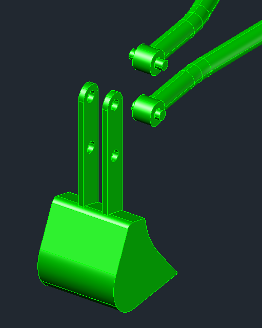
The revised rivet design draws inspiration from Technic pins used in LEGO models. The two pegs insert into a designated opening, compress during insertion, and return to their original shape once fully seated. While the rivet is able to spin freely, it requires significant force to remove, making it well suited for holding the arms securely in place.
The overall dimensions were established by studying existing examples, modeling multiple variations, and printing small test pieces to evaluate potential improvements. I personally tested three iterations of the rivet, focusing on aspects such as peg length to ensure proper bending. Additionally, I refined the hook at the end of the pegs to find the ideal size that allows for easy removal while still preventing the rivet from coming loose under a light pull.
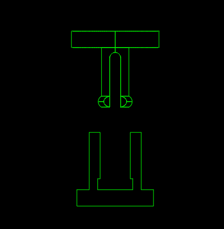
Shovel Hinges
The two hinge locations for the shovel in version 1 were held together with rods and tight fit rivets at each end of the rod. To avoid more tight fits, the rivets were swapped out entirely for little pegs printed directly onto the ends of the arms. These pegs fit into the shovel hinge holes by prying the narrow plates apart and sliding them in between.
This method of fit relies on the properties of the filament used for printing. PLA was used in testing all printed parts, and as I began fitting everything together I came upon the solution by accident. While trying to disassemble the shovel in version 1, the rod on either side of the shovel broke while remaining wedged in between. The narrow plates had to be pried apart to get the shovel off, which lead to the though, “how about I make it easy and design the hinge to work exactly this way”. It functions as a design reminder that accounting for material properties can often lead to solutions approached from different angles.
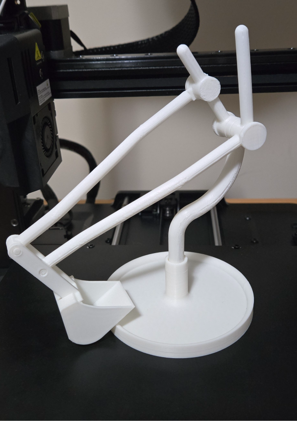
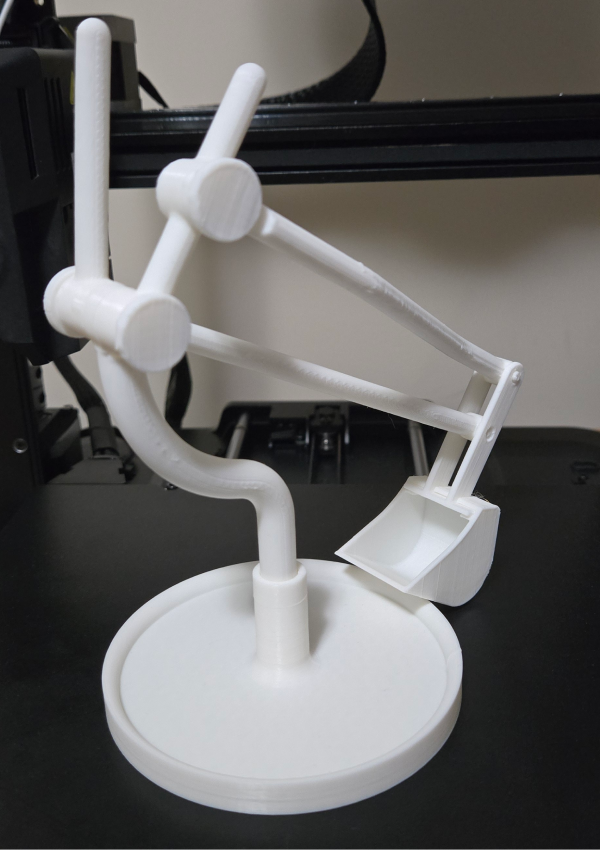
Finished Look
Now lets review the completed Version 2 after it has been printed and assembled.
Key learnings
For Version 2 of the excavator, the major improvements that made the print a more reliable mechanism came from identifying where tight-fit connections were necessary versus where loose-fit connections were more effective. This process involved dissecting each component to realize that some were needlessly overdesigned, while others still required more thought for better functionality. Overall, the best way to discover these flaws is to ultimately produce a print and see where they present themselves. If things don’t work out the way you expect, think it over, do some research and find a better solution
Other Considerations
As I was making the changes from version 1 to version 2, a consistent aspect stuck in the back of my mind, which was to design everything for easy disassembly. If an individual piece breaks, it is much easier to repair by reprinting only the damaged part rather than reprinting the entire assembly because the connecting joints were locked together. Designing around disassembly was definitely the goal for Version 2, but Version 3 will present a heavy emphasis on attempting to reduce filament use. For more information on how this is done, wait for the next post for Version 3!