Engineering offers a wide range of fields for specialization, along with numerous areas of discovery that can spark new interests for those eager to dive into fresh challenges. As I’ve developed a newfound interest in mechanisms and motion structures, I dove straight into a textbook focused on the mathematics and schematics of the topic. However, I soon found myself asking, ‘What do these calculations actually represent?’ and ‘How do they relate to the real-world outcomes of the mechanism?’ It’s one thing to take values and plug them into an equation to get a result, but it is another thing to truly understand what these values mean and how all the pieces interact with each other as a whole. I decided to shift my approach to learning this topic. Instead of focusing on the mathematics, I chose to study the components of both simple and complex mechanisms, aiming to understand how the parts interact and work together to achieve the desired outcome. This entry aims to provide a takeaway on how to approach a new concept by breaking it down into simpler, understandable components, allowing it to make sense intuitively rather than relying solely on reading through complex calculations. Although your new interest in engineering may be from a different branch, this may provide some ideas in how you can approach yours as well. As this is first dive into Mechanisms, some of the correct terms may be referred to as something else.
Exercise 1 – Breaking down a Hoberman Sphere
Lets start at studying a popular motion structure, the Hoberman sphere. This popular toy can show us a lot about some simple concepts about how two connected pieces in motion can transfer the direction of that motion to another segment.
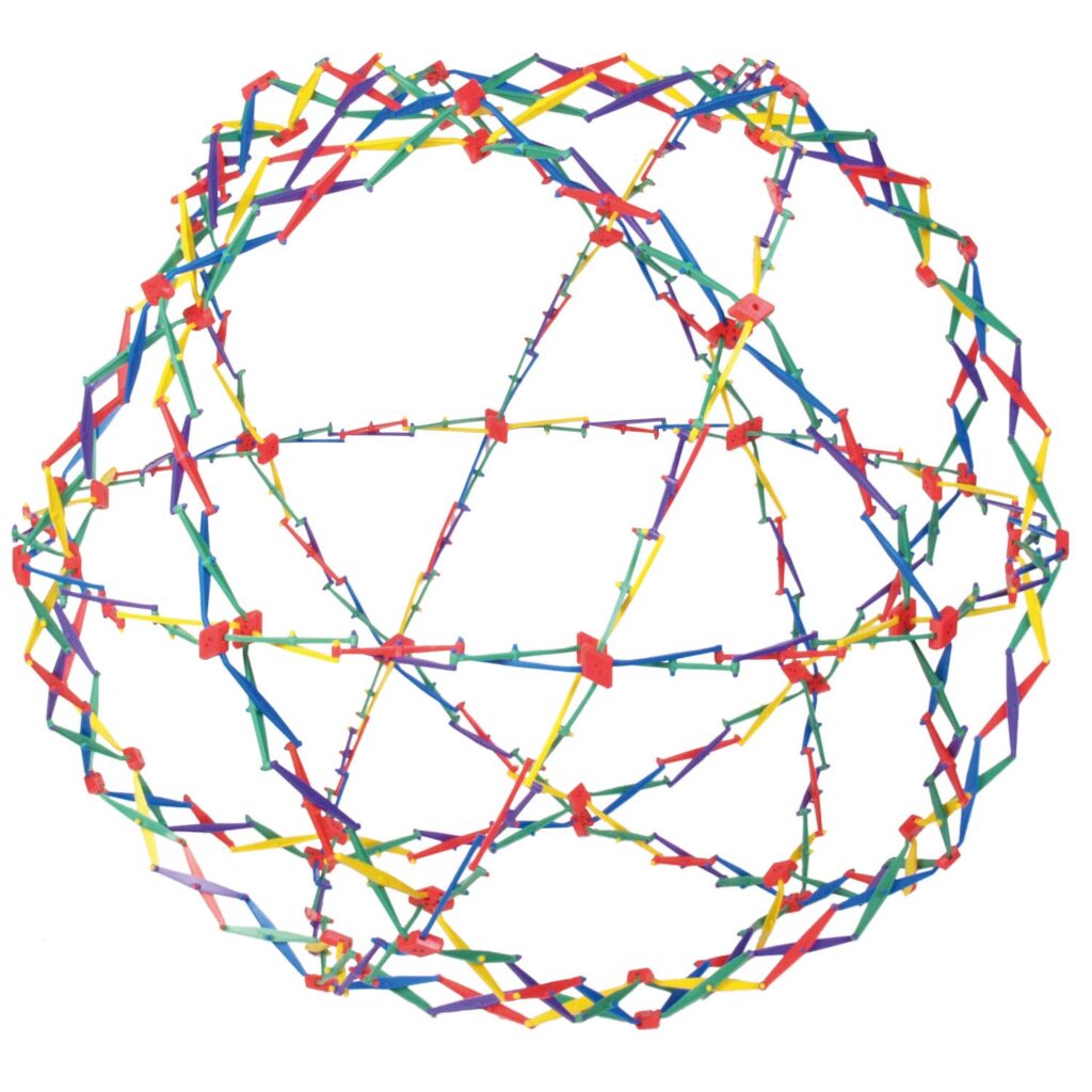
This complex looking structure can be broken down into simpler concepts to get an understanding of how everything fits together. As can be seen in the image, the series of connections forms a complete ring around the perimeter of the ball. The ball is actually comprised of several rings that are rotated and shifted around, and the intersection points of each ring is connected to give the structure a three dimensional frame. Lets look at a profile of one of these rings and inspect it further.
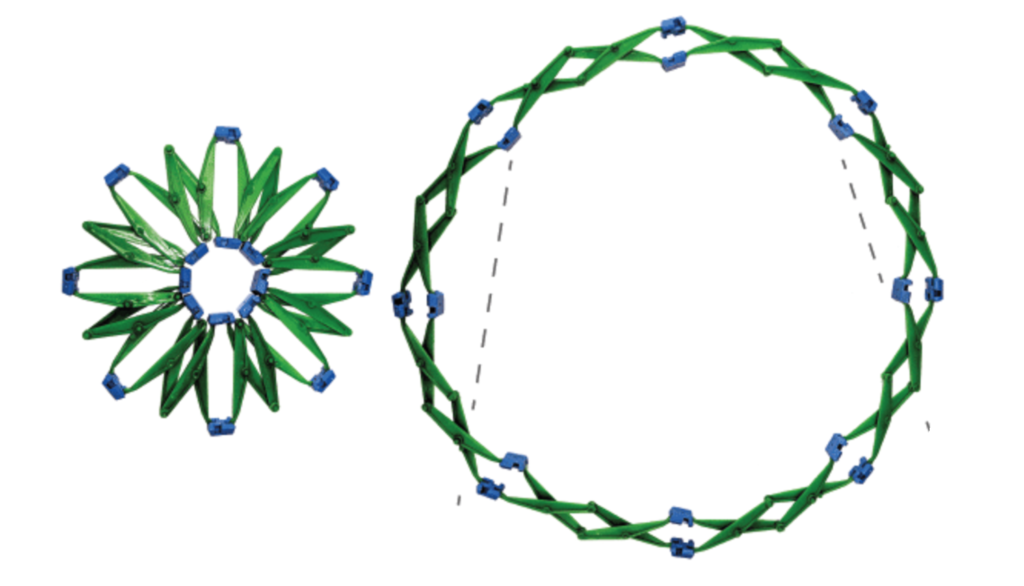
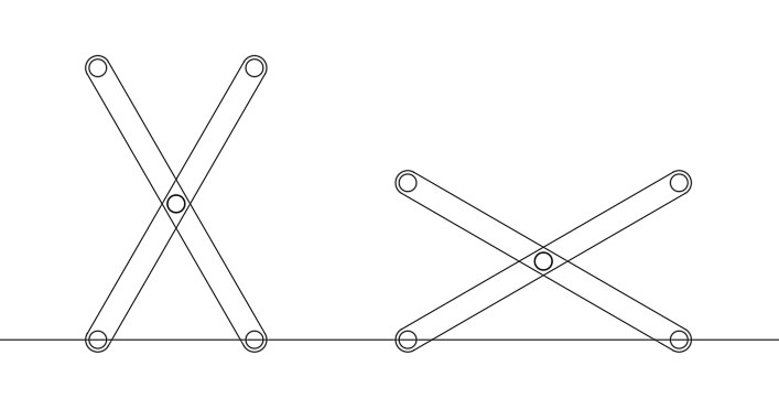
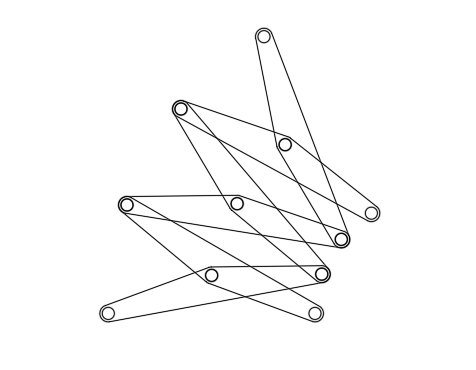
The profile of these rings actually comes from a smaller version of the Hoberman sphere, containing less connections, but will serve the same purpose for this exercise.
We can extrapolate a few take-aways form this image of the ring profile;
- The same type of connections are used consistently around the ring.
- The positioning of the joints are designed so that any rotation on the hinges will cause the ball to expand or compress.
- The geometry of the hinges to lengths of components matter to the workings of the sphere.
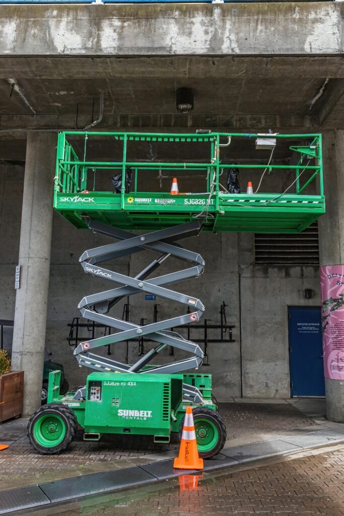
Since the same type of connections are used through the whole ring, we just need to understand how this one type of connection works, making things a bit easier for us. The next thing is to see how the joints interact to expand and compress the ball. When looking at these joints, they make me think of another mechanism that operates similarly to this one, the arms of a scissor lift. In a scissor lift, the arms are connected at their midpoint by joints. When the base of the lower arms is moved closer together or further apart, the top of the scissor mechanism is affected, causing the load to move higher or lower. This mechanism is called a scissor linkage, and is used not just for a scissor lift, but in other fun toys that work in the same fashion.
Looking back to the Sphere, the linkage arms works very similarly, except that the transferred motion does not move in a perpendicular line from their relative base, but is angled from their relative base, which is caused by an offset positioning of the joint along the arm.
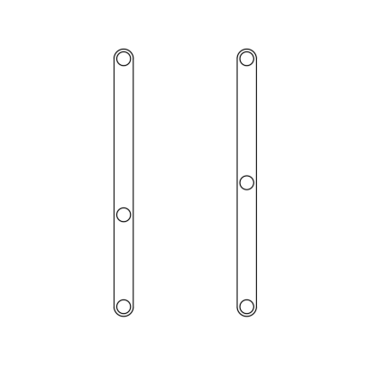
At first, I assumed that what caused this was the change in positioning of the joint along the line of the arm. When testing this out in sketching this concept out with drafting software, I found that the result of transferred motion behaved differently that what I had anticipated. In one of the arms, I kept the joint at it’s midpoint, where as for the other arm, I moved the joint to be further down from it’s midpoint. When the two arms are joined together and rotate at the joint, the direction of the transferred motion changes as the base of the arms move closer together. This is a different construction compared to what is used for the Hoberman sphere.
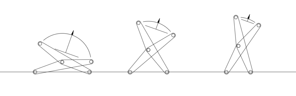
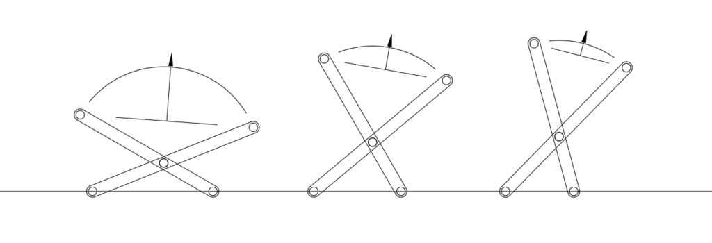
In the Hoberman sphere, the joints are located at the midway point along the length of the arms but are offset from the middle along the width of the arm. The afftect that this has is that when the connected joints are rotated on the connection, the direction of transferred motion is angled away from the perpendicular of the base, but that angle remains consistent regardless of how far apart the arm bases are from each other. This concept is applied to forming a full ring with a series of these linkages connected, as with each one, the direction of motion is angularly shifted from one to the next.
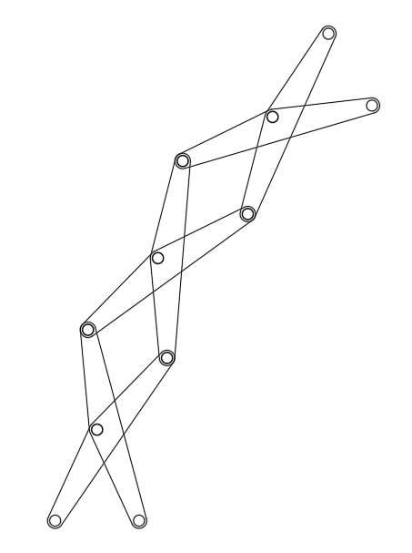
From here, we can begin to get an idea of how the sphere is constructed from a series of these connections working in tandem with each other.
Exercise 2 – Breaking Down a Knuckle Joint Press
Now lets review another mechanism and study its components to intuitively understand how it works, the knuckle press. A knuckle press is a type of industrial equipment used primarily in metalworking and manufacturing. It is used to apply precise pressure or force to a workpiece, often for pressing, forming, or shaping materials. The term “knuckle press” refers to the design of the machine’s knuckle-joint mechanism, which allows it to apply force in a controlled and consistent manner. This type of press typically operates using a combination of mechanical arms and a knuckle joint that helps distribute force evenly.
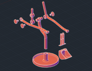
Focusing only on the core mechanism, a schematic of the basic structure is provided below, with all other components removed to show the basic workings.
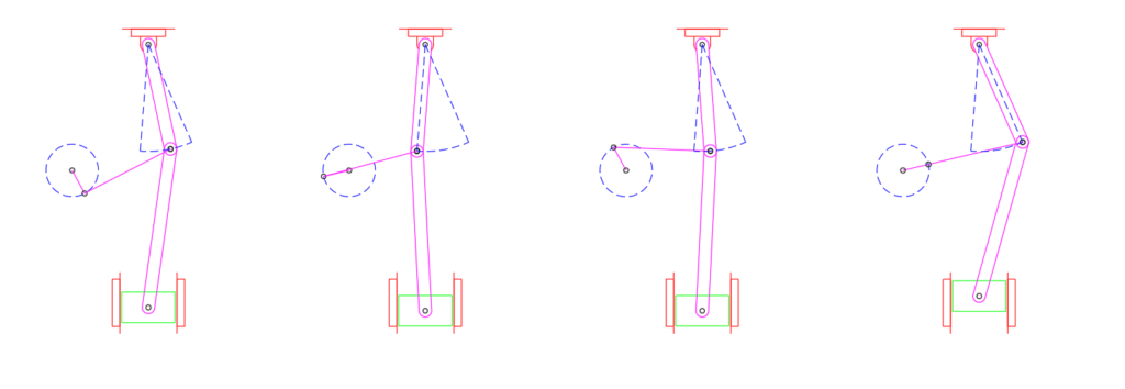
While reviewing the workings of this mechanism, it seems to come pretty easily in understanding how everything works together; the crank rotates, which pulls the coupler, which lifts the ram along its up and down trajectory. The next step to take is sketching out the pieces and understand how the shapes specifically work together to succeed in the motion of the knuckle joint press. To begin understanding the inner workings, I began drafting a similar Knuckle Joint Press. I designed the components to ensure the mechanism lifts the ram along its expected trajectory, illustrating its starting position and mid-cycle states to represent the points where the ram reaches its lowest and highest heights.
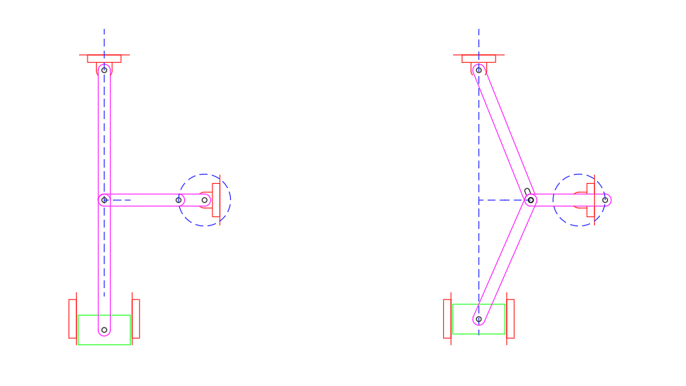
For my sketch, let’s use the same terminology as shown in the image above. When comparing the two, you may notice a difference in the connection point between the rocker and the coupler. In my sketch, I’ve included a slotted hole for this connection, as a fixed connection won’t work in this case due to the specific geometry and how the components interact with each other. If you were to rotate the rocker in a case of it not being connected to anything else below it, then you will see that the length of the rocker is a fixed constant.
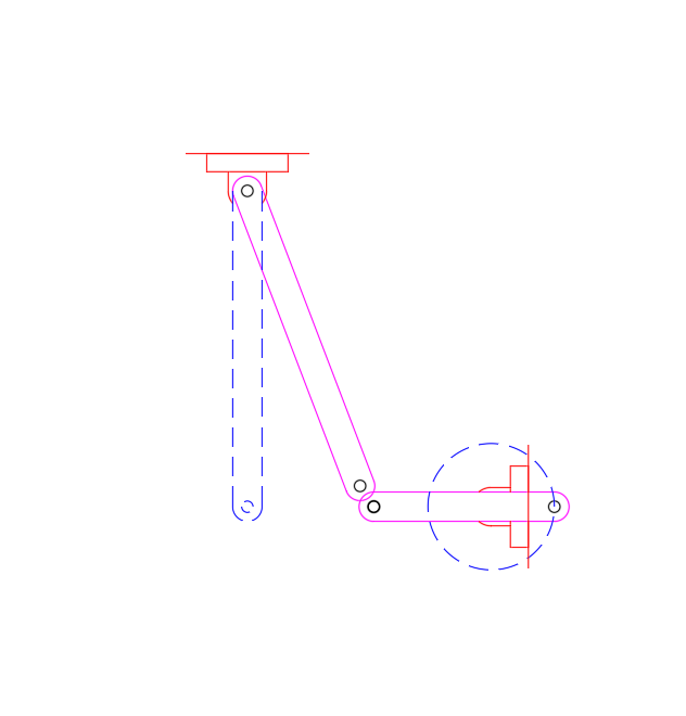
As seen, with the rotation of the rocker, if the end of the rocker and the coupler were to connect at this point in the cranks cycle, then it’s length would have to be increased for that to be possible. For this point I added in a slot so that this mechanism could work if it were to actually be built. The first image of the knuckle joint press does not include this detail, but as it is an image to provide the concept, it should be taken too literally.
After this realization, I researched how knuckle joint mechanisms appear when assembled and functioning in real-world scenarios. From my findings, I discovered that these mechanisms typically don’t use a slotted hole for the connection. Instead, throughout the full cycle, the rocker and the second coupler (the one connected to the ram) extend beyond their aligned point to accommodate the full rotation of the crank.
To define the geometry and ensure everything would connect properly, I began by illustrating the total height I wanted the ram to travel during its cycle. Next, I determined the necessary range of motion for the rocker and coupler throughout the full cycle. From there, I selected a point for the crank placement, traced its arm length, and mapped out its 360-degree rotation. Then, I connected the mechanism, making small adjustments as I went along.
By sketching the operation of the knuckle joint press, I was able to identify key factors that contribute to its functionality and create a basic model using concepts of descriptive geometry to connect everything together. This process helped build an understanding of the important factors and how they interact, making our intuition for designing a real knuckle press more accurate and reliable if we were to actually design one. As mentioned, the use of descriptive geometry was very helpful in ensuring that all components aligned properly and lead to the conclusions of this exercise. For more information about descriptive geometry, A discussion of the basics concepts can be reviewed in a previous post of mine; https://draftingiteration.com/the-simple-and-overlooked-applications-of-geometry-in-design/
Conclusion
Learning a new branch of engineering can feel overwhelming at first, but by breaking down an established design in any field and trying to understand the function of each component, it becomes much easier to grasp. By following these steps to help newcomers understand mechanisms and motion structures, I hope you found this approach engaging, informative, and that perhaps it inspires you to take the first step in learning something new. If you would like to add to the conversation, or share your own stories to approaching a new topics, then please leave a comment.