For a designer who regularly uses AutoCAD in their daily tasks, using the software can eventually become second nature—easy to navigate and intuitive. As you grow more familiar with it, you’ll begin to notice both its strengths and its limitations. One area where I found AutoCAD to be limiting is in its ability to create 3D models. While it handles basic tasks like sketching, extruding, and joining objects well, it struggles when it comes to modeling objects with complex curves, asymmetrical features, and more intricate shapes. The kinds of 3D objects that you can find easy to model would be those constructed form prisms or extruded sketches that are combined together, but it would be difficult to model something with curved features, like a sports car. For answers to this, I looked out to trying another software that allows for more intricate modelling and came across Autodesk Fusion. After looking into the possibilities it offers, I delved in to practicing with it and providing my feedback. Here are some of my experiences, along with some tips and tricks that I found that might make a better experience for other beginners to Fusion.
Fusion – Complexity Level for Beginners
Before reflecting on my experiences as a beginner, I should mention that having primarily worked with AutoCAD, I’ve developed a specific train of thought regarding how I approach 3D modeling. This definitely influenced how I dove into this process. A beginner with little experience in AutoCAD may find learning Fusion much smoother. As for me, I found shifting from one modelling style to another to be difficult and would find myself asking, “why can’t you just do it like this”, or, “why is it making this so needlessly difficult to do?” This may come from a mindset of modelling with more simplistic functionality. When digging more into Fusion, although frustrated, I began to realize that Fusion has so many of these ‘restrictions’ to give more precise control to your 3D model. It simply requires understanding the features and using the rules of those features to approach how you should build something with them. It is these features, while difficult to absorb at first, is what will give you the control required to build something much more complex than joined prisms and simple extruded objects.
Beginning the Practice Project – Beginners Tips
To develop strong proficiency in modeling software, it’s best to create a practice project and use the software from start to finish. I designed a project to model a desk toy of my own creation. The toy is inspired by a drawbridge, where pressing down on the base causes the bridge to open and close.
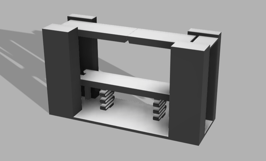
Shown here is the first iteration of the draw bridge, and at it’s current state it still requires some rework, testing, and some aesthetic refining. This stage of the drawbridge, as shown in this post, focuses on ensuring the mechanisms function correctly before proceeding further with fine tuning.
As mentioned earlier, I used Autodesk Fusion to model this project. Initially, it was challenging to grasp, but after bringing the model to its current state, I’ve started to appreciate the advantages of using this software to create 3D shapes. In this article, I will start with a brief overview of the design before highlighting key Fusion functions that were especially useful in bringing the drawbridge to life. I will also explore some of these functions’ lesser-known functionalities that may not be immediately apparent. These functions include:
Components – How to separate and organize the individual pieces in your project
The Measuring Tool – How to use this command and how it interacts with objects to get the best use from it
How points work in relation to the origin – Some in depth information in manipulating objects along an axis
How to move objects – I have found that the way to move objects does not work nearly the same way that it is used in other 3D modelling Software.
Starting the Project – Design and Iterating
At the first phases of the draw bridge in figuring out the geometry and the mechanics of it, I opted to use basic AutoCAD instead of using Fusion for this part. I found that AutoCAD was a better way to approach the multiple mini iterations in the control you get with the basic 2D objects instead of the constraints that is used through Fusion. However, I acknowledge that this could be in part of the fact that I am more used to using AutoCAD over Fusion. But for now, lets go over some of the mechanics that I decided to incorporate into the draw bridge design
Info Drop – Constraints are rules you can place on your 3D objects that control the relationships between sketch geometry, ensuring precision and consistency in designs. They help maintain the intended shape and behavior of a sketch even when dimensions change
To begin, I started by doing some quick research to see how a draw bridge actually functions. There are few different types of draw bridges:
Bascule Bridges – this type of bridge operates like a seesaw and used counterweights on one side of the seesaw hinge to raise the other side of the section of the bridge.
Swing Bridges – This bridge has a swivel located at the mid point of the bridge which the rotates horizontally to allow boat traffic on either side of the swivel to pass by at the opened ends.
Vertical Lift Bridges – This lifts a section of the bridge straight up using structural towers and counterweights.
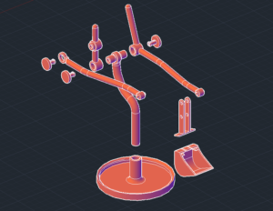
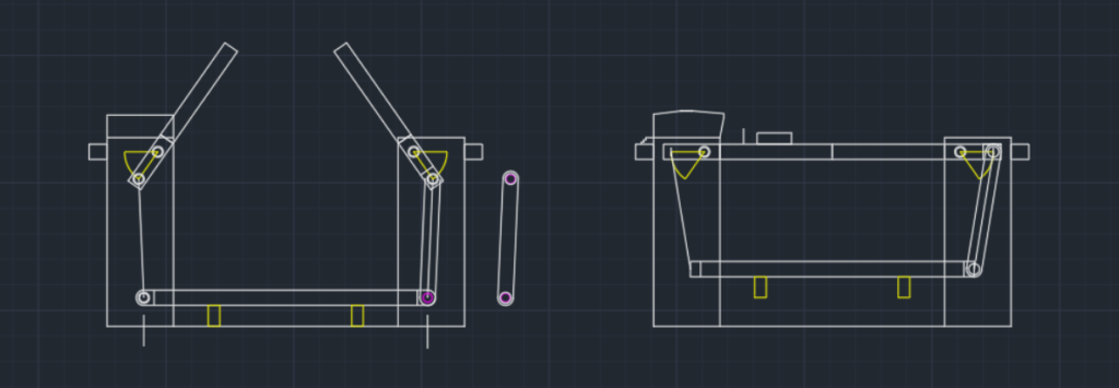
There are some other subtypes to each of these classes which are interesting in their own respect, but as seen in the design I opted for, I chose to design this desk toy to closely mimic the functions of a bascule bridge. Rather than using counterweights to raise the bridge, I made a simple hinge and lever that is attached to a base that, when pressed down, will raise the bridge. When sketching out the geometry for the mechanisms, I determined some guidelines that I wanted to stick by and used those for the design parameters. Here are some of the parameters that I used in designing the draw bridge, take a look at the image ands see where you can point out where each one of these were utilized:
Length of the Bridge and Height of the Towers – The geometry of the bridge length with the towers is the starting point to the design. This all determines how much the bridge will lift by and how much rotational movement is required.
Maximum Height of the Raised Bridge – Determining the maximum height of the bridge will set the range of rotational movement between its initial resting point and max lifting point. This rotational range can be seen in the sketch above in yellow at the hinges. The length between the hinge and the pin will determine the required downward force to lift the rising end of the bridge. To reduce this force, the length between the hinge and pin can be increased but will require a longer travel distance at the hinge. Since this is a simple desk toy, I decided not to focus too much required forces, but would benefit with addressing this at later iterations.
Distance of vertical travel for the base – I set this vertical travel to be within a comfortable range for someone’s finger to be tapping on the top of the base.
Hinge and lever arm length – The setting the rotational range and the travel distance of the base left with a given length for the lever arm. I wanted to situate the arm so that at the bridges raised position the arm will not go past 90 degrees to prevent seizing up or rotating backwards. The pegs underneath the pressed base prevents the base from lowering too far and prevents backwards rotation. This required a bit of tweaking to the other variables to get it right.
Resetting the bridge to its horizontal position – To reset the bridge, I opted to go with using a spring to simply set it back. I would have to design a spring that would require it’s fixed length to match vertical space of the underside of the base and top of the stationary base.
With the geometry of all the pieces in place, it was time to take this information from AutoCAD and to use it in modeling the draw bridge in Fusion.
Using Fusion for 3D modelling
The majority of the time spent modeling the drawbridge was dedicated to learning how to use Fusion 360 and understanding the best ways to leverage its features. When working with any software, there is a sort of unspoken method and sequencing that the software prefers to get the user to follow in order to make best use of it. For example, when working in AutoCAD, it’s best to approach an object by realizing how much of the object should be worked in 2D before extruding it out into a 3D object. It’s better to work out an objects geometry in 2D as much as possible, as AutoCAD works great in 2D elements but is just sufficient with 3D objects. You can manipulate 3D objects with additions and subtractions, but when you create the 3D object, it is very much a ‘Dummy’ model and doesn’t have much dynamic functioning behind it. This can make it frustratingly difficult at times to work 3D objects after they are complete, which means that you better get your object correct and hope it doesn’t require any changes to it later.
Fusion, in contrast, has much of this dynamic functioning built into the 3D objects. You can set certain constraints to geometry which will keep certain design elements consistent when changes are made to the model. With these constraints, it can seem difficult to use Fusion to an AutoCAD user, since Fusion better benefits from many simple 3D shapes to build up the geometry of something more complicated, in which you can go back and manipulate each of these separate object later on. This does technically make it simpler to create any 3D object you want in Fusion. When you’re accustomed to creating objects in a particular way, it can be challenging to adjust your process and work efficiently in a new environment that requires a different approach.
Lets go back to the 3D model in Fusion and review.
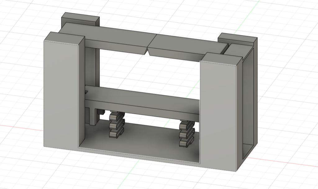
Reaching this point has taken considerable effort (and a fair share of stress), but after completing this revision, I’m starting to appreciate the advantages of Fusion. That said, while Fusion and AutoCAD share some fundamental functions, they are accessed and used in different ways. Through trial and error, I’ve gained insights into these differences—insights that I believe aren’t discussed as much as they should be to make it easier for beginners to grasp. Let’s dive into four key areas that I found useful: Components, the Measuring Tool, the role of points in relation to the origin, and moving objects.
Components
These represent individual parts or pieces within a working file which allows you to create, organize and manage different parts of your project. In a single file, if you plan to model multiple interacting pieces that need to work together, it’s essential to use the components feature in Fusion. If you were to try modeling all the different pieces withing the same component layer, then Fusion will treat every 3D object as a single piece and automatically join them together.
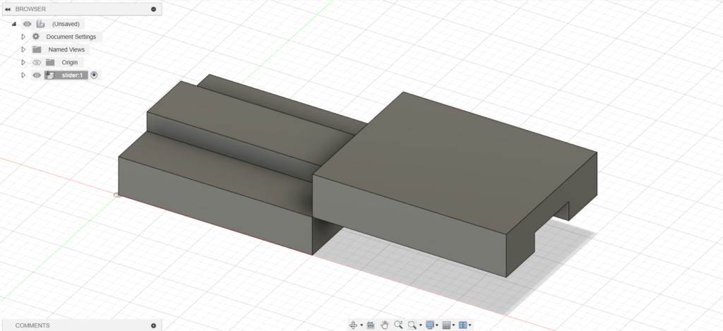
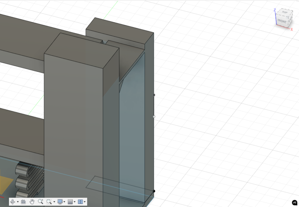
In the example provided here, I made two blocks with a slot between them for them to side and fit together. They are currently on the same component layer, which can be seen in the drop down list highlighted as “slider 1”. When creating the top block, I drew a box around the edge of the slot to make a shape that then could be extruded.
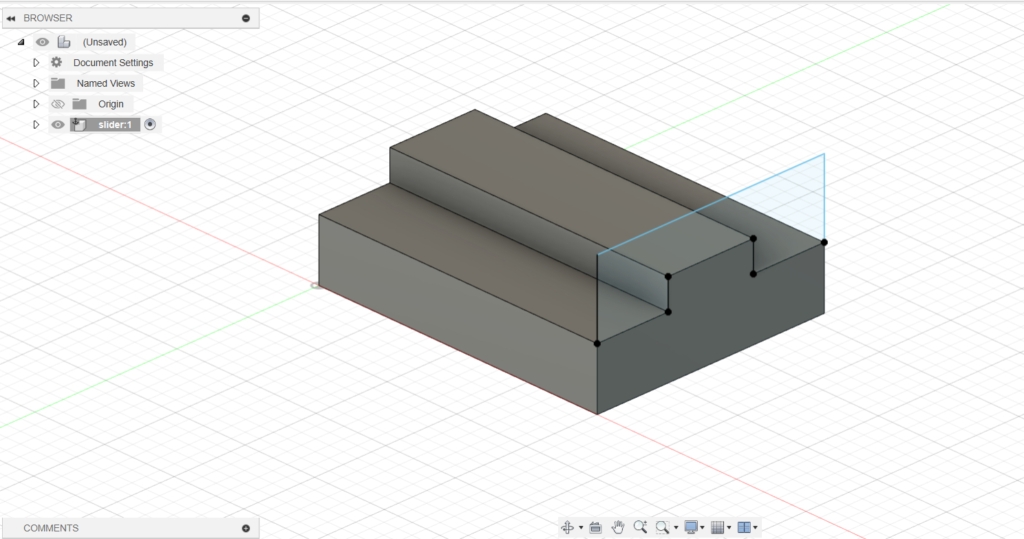
If you were to extrude it in the direction towards the left of the screen, fusion will not treat it as an individual object, but as an object that should be combined with the bottom block.
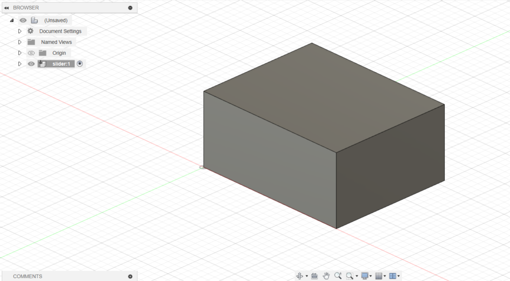
This is because the top block was not set to it’s own component layer. There may be some ways to keep 3D objects as separate entities under a single component layer, but it is highly encouraged that pieces intended to be different pieces should be set to their own component layer.
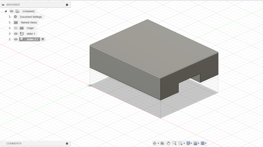
As a key rule, if you are making a 3D object that is part of another object, keep this under the same component. If it’s intended to work as individual pieces, then set it to its own component layer.
The Measuring Tool
The measuring tool works a bit differently from AutoCAD measuring, but can have better utility once you get used to it. Since objects you create are all dynamic, you can click on a specific surface, edge, or point to get a specific value with less clicks.
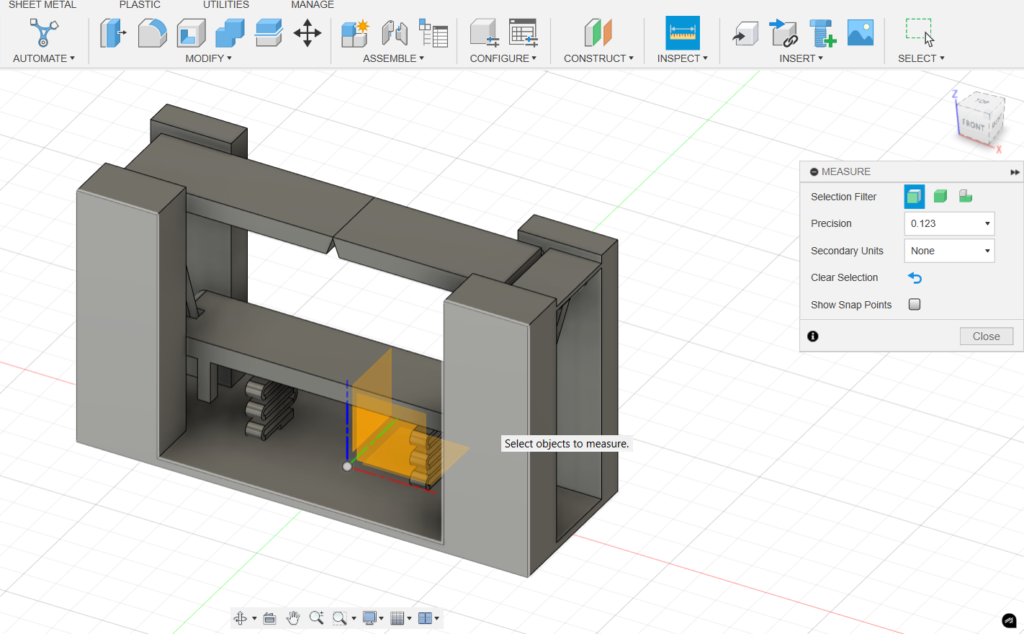
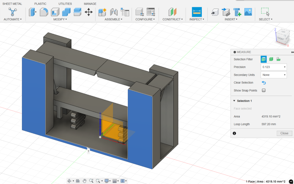
When selecting the measuring tool under ‘inspect’ hover the curser over a whole surface to see it highlights in white, which will be the surface it will calculate. Click on the surface and get values like the area and loop length
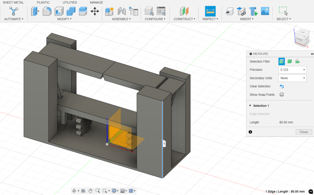
The same can be done with line and points, giving you the option to fine tune the geometry that you want to pull dimensional information from.
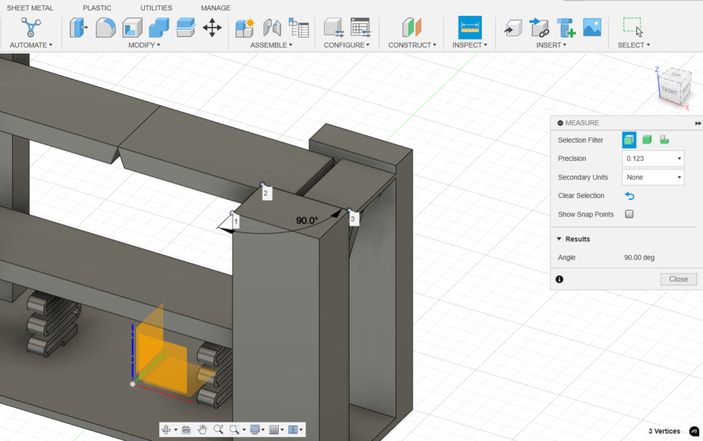
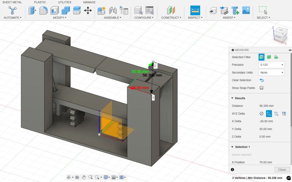
When measuring point by point, you can click a series of more multiple to review varying information between the geometry of where those points are positioned from each other.
The Role of points in relation to the origin
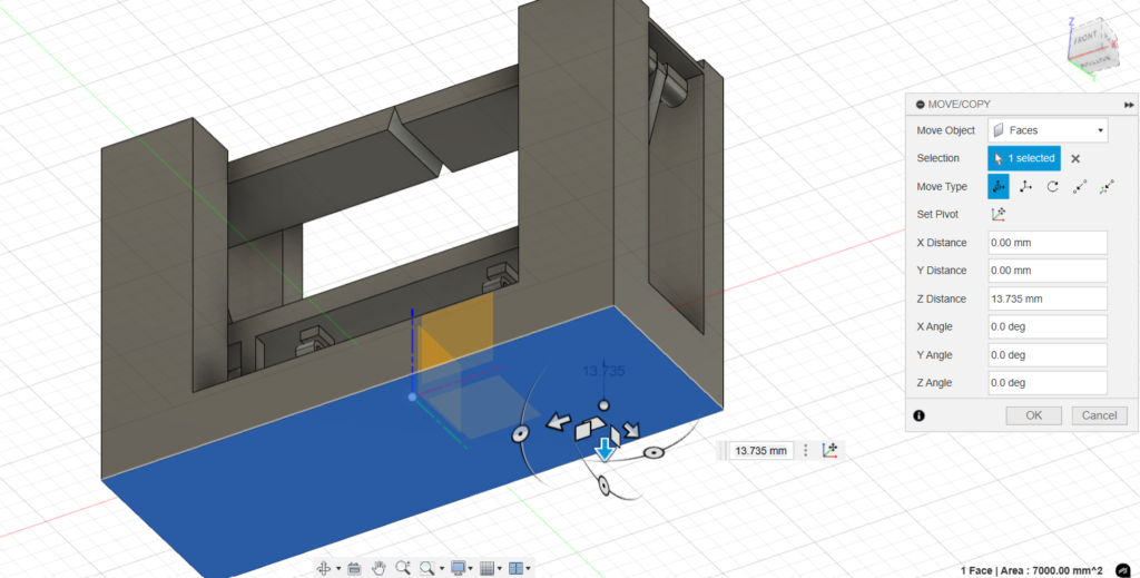
understanding how points relate to the origin is an easy lesson that will help prevent you from having to undo object maneuvering many times. In this screenshot, you can see that as I am attempting to stretch the underside of the base to give it more thickness (see the view cube in the corner to tell that it’s the bottom). You’ll see that the direction of the stretch is in the Z direction, and based off the grid, it should be a negative value, but the value in the move box shows it as a positive value. This is because Fusion will base your negative and positive movement values by the surface that you are selecting and not necessarily by the change on a grid.
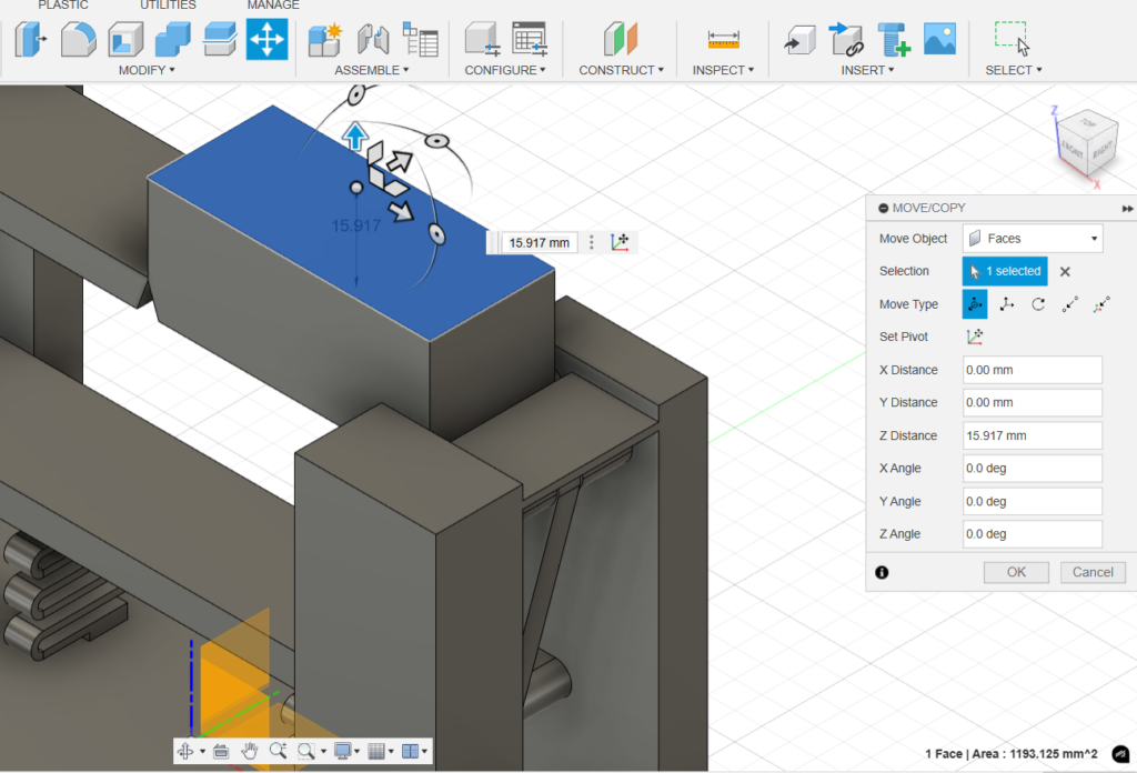
This can be confusing if you’re used to moving objects in AutoCAD. In AutoCAD, when using the move command, you can control the direction of an object’s movement by simply moving the cursor in the desired direction, regardless of whether it’s a positive or negative movement on the grid. In the next screenshot, you’ll see that I’m trying to shift the surface downward, so I move my cursor down to move the surface in that direction. However, when I override the movement with a set value and hit Enter, the surface actually stretches upward instead.
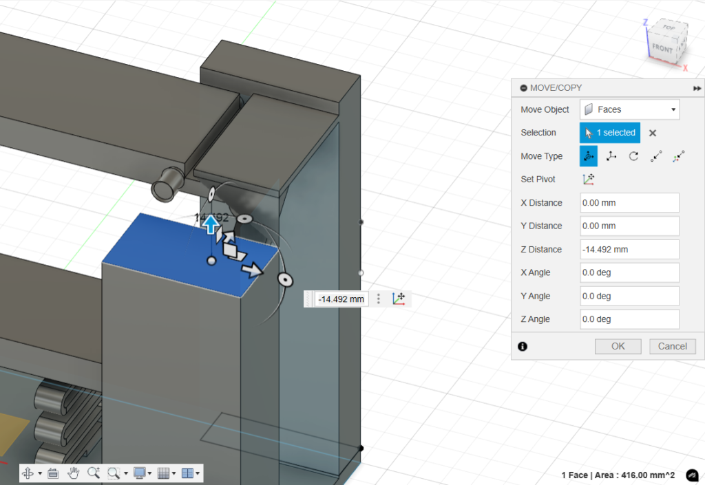
This is because you must specify the direction of the movement as either a positive or negative value in relation to the surface that was selected. A good rule of thumb when making adjustments like this is to pay attention to the direction of movement you intend and whether Fusion has recognized it as negative or positive. This will help you avoid having to undo many adjustments.
Moving Objects
This function can come across as unintuitive, and possibly frustrating, to use at first, but there are certain elements at play that may affect the ease of moving using this command. To use this command, select it in the top toolbar, or right click and access it through the rotational selection wheel .Since all objects are dynamic, you should be intentional on what variable of an object you want to modify or move. Selecting a corner, face, or point of an object does not designate to Fusion that you want to move the whole object, rather, you will find yourself moving one point or one face while the rest of the object remains stationary.
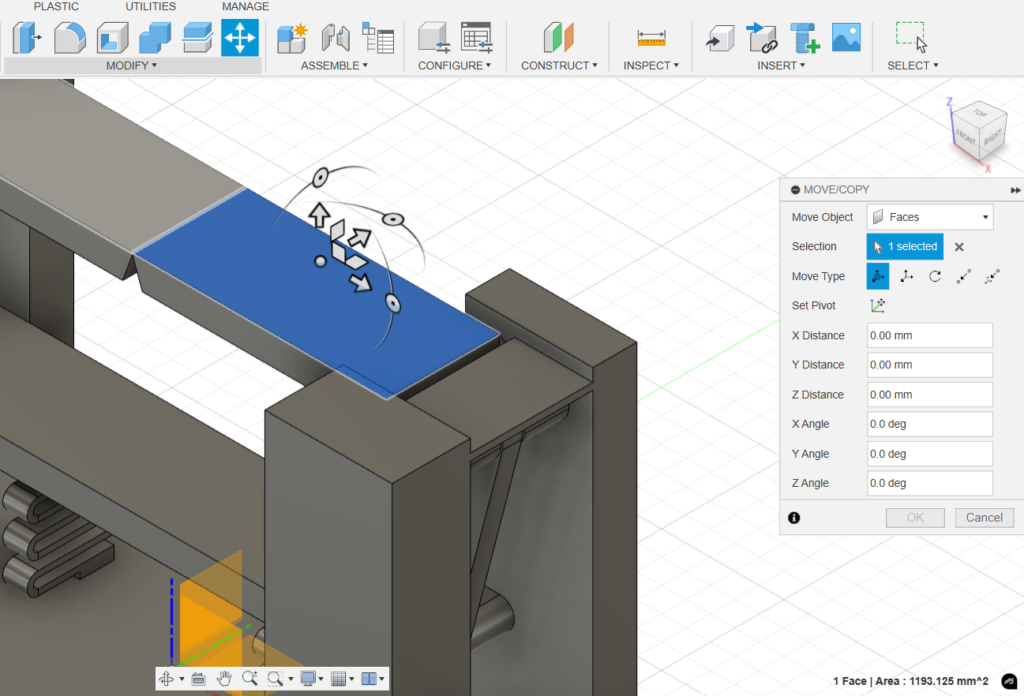
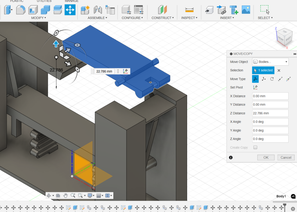
As shown here, I only selected the surface of the object, which then makes a modification in only that surface and not the whole object. To work around this, it is easier to drag your curser across the object so that it highlights most of the objects features. This then makes moving the object easier without accidentally making unnecessary changes to the object itself.
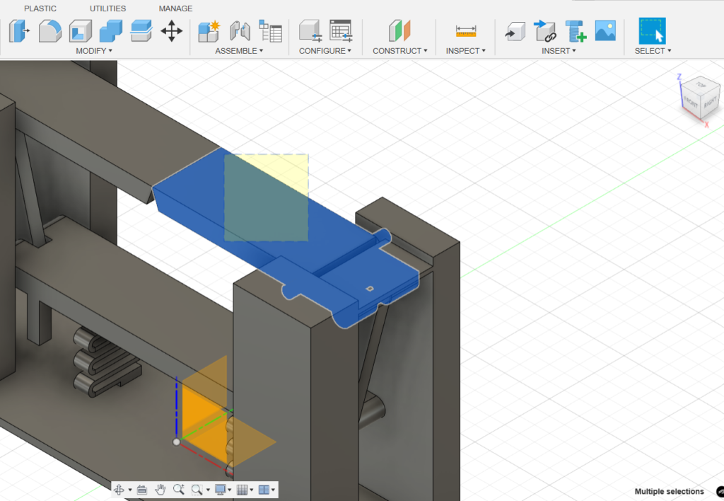
If you find yourself accidentally selecting other components behind the object you want to select, you can try hiding the other components in the component layer manager on the left of the screen.
If, after following these steps, your object still won’t move, take a moment to check if it is constrained by other components, sketches, or objects. While constraints can be useful for maintaining specific geometric relationships between interacting shapes, they can also limit the ability to move objects independently. For instance, if a circle is constrained to the center of an edge but you want to move it separately, review the constraints in the sketch editor and remove any that are limiting its movement. ( in the screenshot, the rectangle icon shows that the circle is constrained to the center of the rectangles edge)
Conclusion
Learning how to use new software can feel overwhelming at first. In this post, I shared some tips for using certain Autodesk Fusion commands that I initially found less intuitive. I also introduced the drawbridge desk toy project, a fun design that involves extensive use of Fusion. In the next installment, I’ll showcase the next iteration of the drawbridge desk toy and dive deeper into its design and even try to find a way to implement 3D printing. If there’s anything you’d like to know more about that wasn’t covered here, feel free to leave a comment and start a conversation!